7-38
2. Remove the security bezel, if any. For more information, see "Replacing the security bezel."
3. Remove the compute module. For more information, see "Removing a compute module."
4. Remove the compute module access panel. For more information, see "Replacing a compute
module a
ccess panel."
5. Remove the riser card and PCIe module in the compute module. For more information, see
"Replacing the riser card and PCIe module in a compute module."
6. Remove air baffles in the compute module. For more information, see "Replacing air baffles in a
comp
ute module."
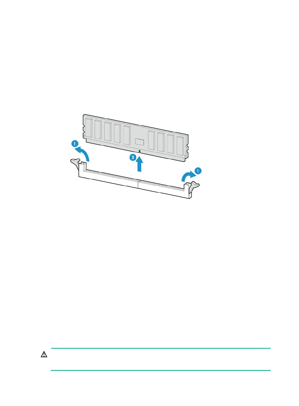
7. Open the DIMM slot latches and pull the DIMM out of the slot, as shown in Figure 7-43.
Figure 7-43
Removing a DIMM
8. Install a new DIMM. For more information, see "Installing DIMMs."
9. Install the removed air baffles in the compute module. For more information, see "Replacing air
baffles in a compute mo
dule."
10. Install the removed riser card and PCIe module in the compute module. For more information,
see "Installing a riser card and a PCIe module in a compute module."
11. Install the co
mpute module access panel. For more information, see "Replacing a compute
module a
ccess panel."
12. Install the compute module. For more information, see "Installing a compute module."
13. Install the removed security bezel. For more information, see "Installing the security bezel."
14. Connect the power cord. For more information, see "Connecting the power cord."
15. Powe
r on the server. For more information, see "Powering on the server."
Duri
ng server startup, you can access BIOS to configure the memory mode of the newly
installed DIMM. For more information, see the BIOS user guide for the server.
Verifying the replacement
For information about the verification method, see "Installing DIMMs."
Replacing the system battery
WARNING!
To avoid bodily injury from hot surfaces, allow the server and its internal modules to cool before
touching them.

 Loading...


