10-13
8SFF and 24SFF compute modules have the same physical layout of the DIMM slots on the main
board, as shown in Figure 10-12. Fo
r more information about the DIMM slot population rules, see the
guidelines in "Installing DIMMs."
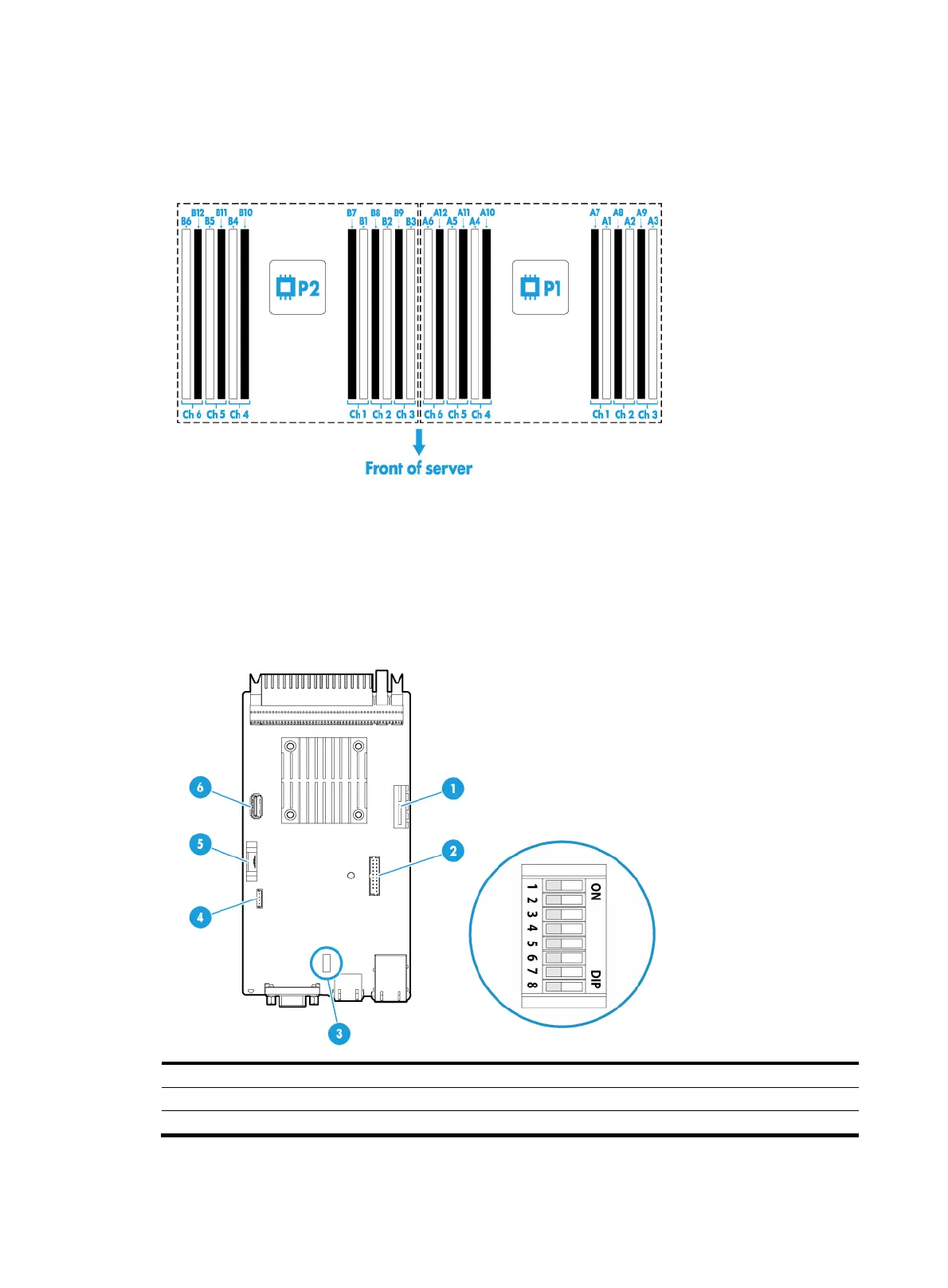
Figure 10-12 DIMM physical layout
Management module
Management module components
Figure 10-13 Management module components
(1) Dual SD card extended module slot (2) TPM/TCM connector
(3) System maintenance switches (4) NVMe VROC module connector
(5) System battery (6) Internal USB 3.0 connector

 Loading...


