10-7
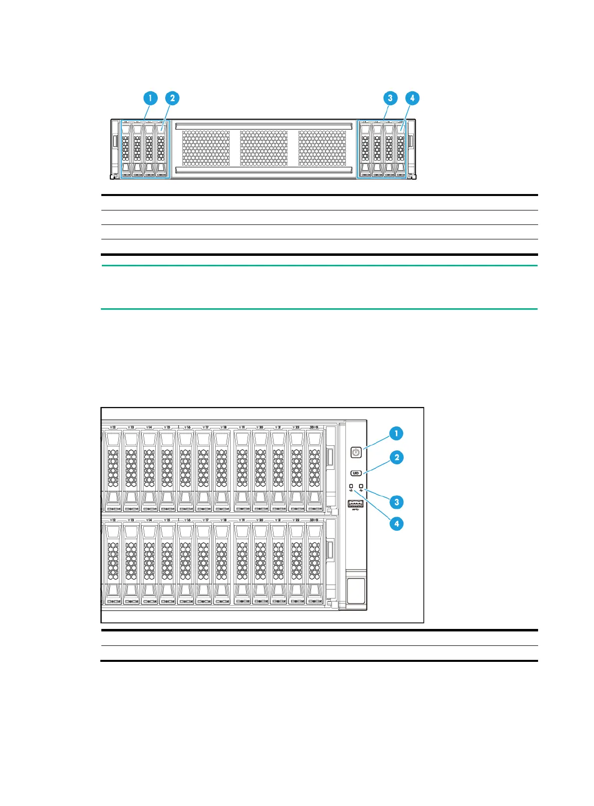
Figure 10-7 8SFF compute module front panel
(1) Drive cage bay 1/3 for 4SFF SAS/SATA or NVMe drives (optional)
(2) Diagnostic panel (optional)
(3) Drive cage bay 2/4 for 4SFF SAS/SATA or NVMe drives (optional)
(4) Diagnostic panel (optional)
NOTE:
Drive cage bays 1 and 2 are for compute module 1, and drive cage bays 3 and 4 are for compute
module 2.
LEDs and buttons
The LED and buttons are the same on all server models. Figure 10-8 shows the front panel LEDs
and buttons. Table 10-3 de
scribes the status of the front panel LEDs.
Figure 10-8 Front panel LEDs and buttons
(1) Power on/standby button and system power LED (2) UID button LED
(3) Health LED (4) mLOM Ethernet adapter Ethernet port LED

 Loading...


