10-9
Rear panel
Rear panel view
Figure 10-9 shows the rear panel view.
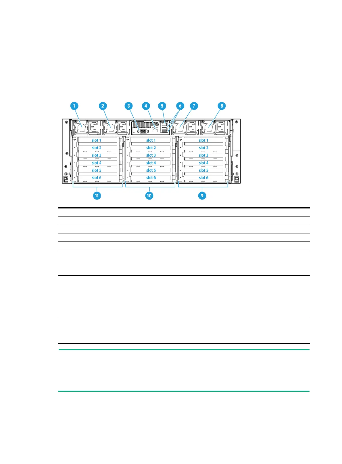
Figure 10-9 Rear panel components
(1) Power supply 1 (2) Power supply 2
(3) VGA connector (4) BIOS serial port
(5) HDM dedicated network port (1 Gbps, RJ-45, default IP address 192.168.1.2/24)
(6) USB 3.0 connectors (7) Power supply 3
(8) Power supply 4
(9) PCIe riser bay 3:
• PCIe slots 1 through 3 (processor 2 in compute module 1)
• PCIe slots 4 through 6 (processor 2 in compute module 2)
(10) PCIe riser bay 2:
• PCIe slot 1 (processor 2 in compute module 1)
• PCIe slot 2 (processor 1 in compute module 1)
• PCIe slots 3, 4, and 6 (processor 1 in compute module 2)
• PCIe slot 5 (processor 2 in compute module 2)
(11) PCIe riser bay 1:
• PCIe slots 1 through 3 (processor 1 in compute module 1)
• PCIe slots 4 through 6 (processor 1 in compute module 2)
NOTE:
• If a processor is not present, the corresponding PCIe slots are unavailable.
• Some PCIe modules require PCIe I/O resources. Make sure the number of PCIe modules
requiring PCIe I/O resources does not exceed eleven. For more information, see "PCIe
module
s."
LEDs
Figure 10-10 shows the rear panel LEDs. Table 10-5 describes the status of the rear panel LEDs.

 Loading...


