6-11
Installing riser cards and PCIe modules
The server provides two PCIe riser connectors and three PCIe riser bays. The three riser bays are at
the server rear and each compute module provides one riser connector. For more information about
the locations of the bays and connectors, see "Rear panel view" and "Main board components",
respectively.
Guidelines
• You can install a small-sized PCIe module in a large-sized PCIe slot. For example, an LP PCIe
module can be installed in an FHFL PCIe slot.
• A PCIe slot can supply power to the installed PCIe module if the maximum power consumption
of the module does not exceed 75 W. If the maximum power consumption exceeds 75 W, a
power cord is required.
• Make sure the number of installed PCIe modules requiring PCIe I/O resources does not exceed
eleven. For more information about PCIe modules requiring PCIe I/O resources, see "PCIe
modules."
• If a processor is faulty or absent, the corresponding PCIe slots are unavailable. For more
information about processor and PCIe slot mapping relationship, see "Riser cards."
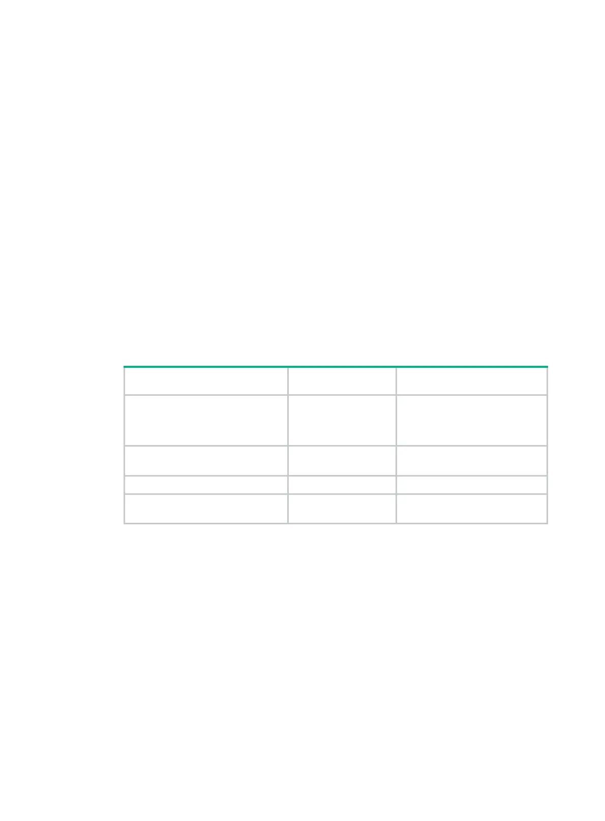
• For more information about riser card installation location, see Table 6-1.
Table 6-1
Riser card installation location
PCIe riser connector or bay Riser card name Available riser cards
PCIe riser connector 0 (in a compute
module)
Riser card 0
• RS-FHHL-G3
• RS-GPU-R6900-G3
(available only for 8SFF
compute modules)
PCIe riser bay 1 (at the server rear) Riser card 1
• RS-4*FHHL-G3
• RS-6*FHHL-G3-1
PCIe riser bay 2 (at the server rear) Riser card 2 RS-6*FHHL-G3-2
PCIe riser bay 3 (at the server rear) Riser card 3
• RS-4*FHHL-G3
• RS-6*FHHL-G3-1
Installing a riser card and a PCIe module in a compute
module
You can install an RS-GPU-R6900-G3 riser card only in an 8SFF compute module.
The installation method is the same for the RS-FHHL-G3 and RS-GPU-R6900-G3. This section uses
the RS-FHHL-G3 as an example.
Procedure
1. Power off the server. For more information, see "Powering off the server."
2. Remove the security bezel, if any. For more information, see "Replacing the security bezel."
3. Remove the compute module. For more information, see "Removing a compute module."
4. Remove the compute module access panel. For more information, see "Replacing a compute
module a
ccess panel."

 Loading...


