7-5
Figure 7-5 Removing the screws on a main board
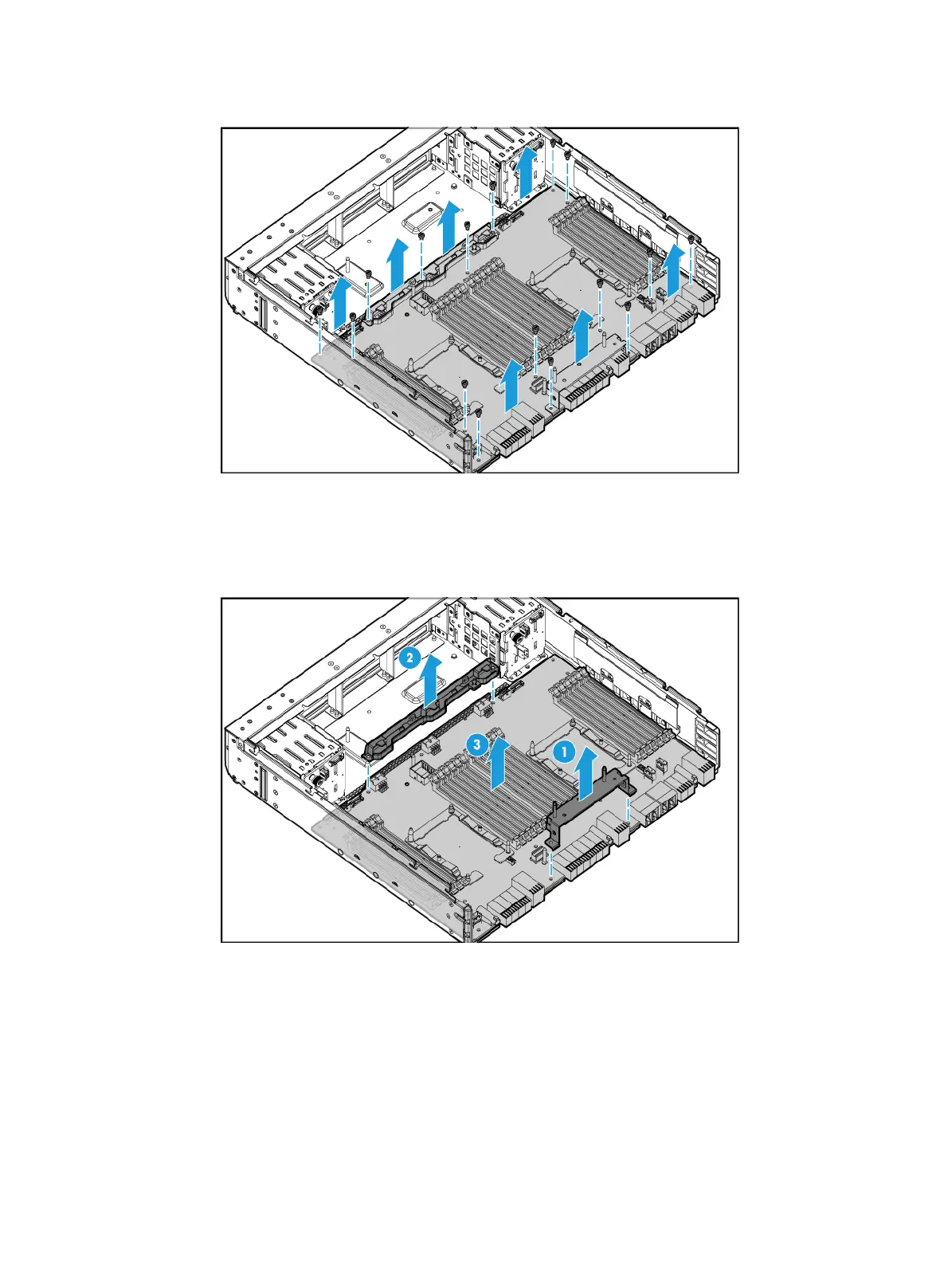
b. Lift the cable clamp and the riser card bracket from the main board, as shown by callouts 1
and 2 Figure 7-6.
c. Lift the main board slo
wly out of the compute module, as shown by callout 3 in Figure 7-6.
Figure 7-6
Removing the cable clamp, riser card bracket, and main board
Installing a compute module and its main board
1. Install the main board in the compute module:
a. Align the installation holes on the main board with the screw holes on the compute module,
as shown by callout 1 in Figure 7-7. The
n, place the main board slowly in the compute
module.
b. Put the cable clamp and the riser card bracket onto the main board, as shown by callouts 2
and 3 in Figure 7-7. Ma
ke sure the installation holes on the cable clamp and the riser card
bracket are aligned with the screw holes on the main board.

 Loading...


