11-8
Model Form factor Capacity Interface Rate Link width
SSD-NVME-3.2T-PBlaze5 HHHL 3.2 TB PCIe 8 Gbps ×8
SSD-NVME-4T-P4500 HHHL 4 TB PCIe 8 Gbps ×4
SSD-NVME-4T-P4600 HHHL 4 TB PCIe 8 Gbps ×4
SSD-NVME-6.4T-PBlaze5 HHHL 6.4 TB PCIe 8 Gbps ×8
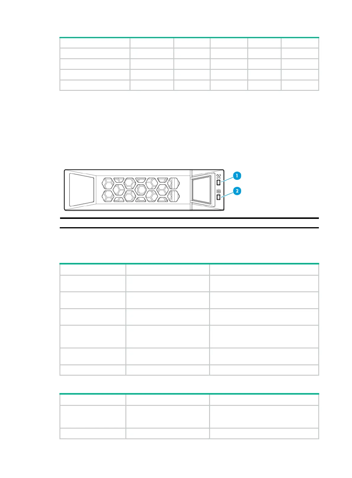
Drive LEDs
The server supports SAS, SATA, and NVMe drives, of which SAS and SATA drives support hot
swapping. You can use the LEDs on a drive to identify its status after it is connected to a storage
controller.
Figure 11-2 shows the lo
cation of the LEDs on a drive.
Figure 11-2 Drive LEDs
(1) Fault/UID LED (2) Present/Active LED
To identify the status of a SAS or SATA drive, use Table 11-4. To identify the status of an NVMe drive,
use Table 11-5.
Table 11
-4 SAS/SATA drive LED description
Fault/UID LED status Present/Active LED status Description
Flashing amber (0.5 Hz)
Steady green/Flashing green
(4.0 Hz)
A drive failure is predicted. As a best
practice, replace the drive before it fails.
Steady amber
Steady green/Flashing green
(4.0 Hz)
The drive is faulty. Replace the drive
immediately.
Steady blue
Steady green/Flashing green
(4.0 Hz)
The drive is operating correctly and is
selected by the RAID controller.
Off Flashing green (4.0 Hz)
The drive is performing a RAID migration or
rebuilding, or the system is reading or
writing data to the drive.
Off Steady green
The drive is present but no data is being
read or written to the drive.
Off Off The drive is not securely installed.
Table 11-5 NVMe drive LED description
Fault/UID LED status Present/Active LED status Description
Flashing amber (0.5 Hz) Off
The managed hot removal process is
completed and the drive is ready for
removal.
Flashing amber (4 Hz) Off The drive is in hot insertion process.

 Loading...


