7-17
a. Disconnect all PCIe cables from the riser card.
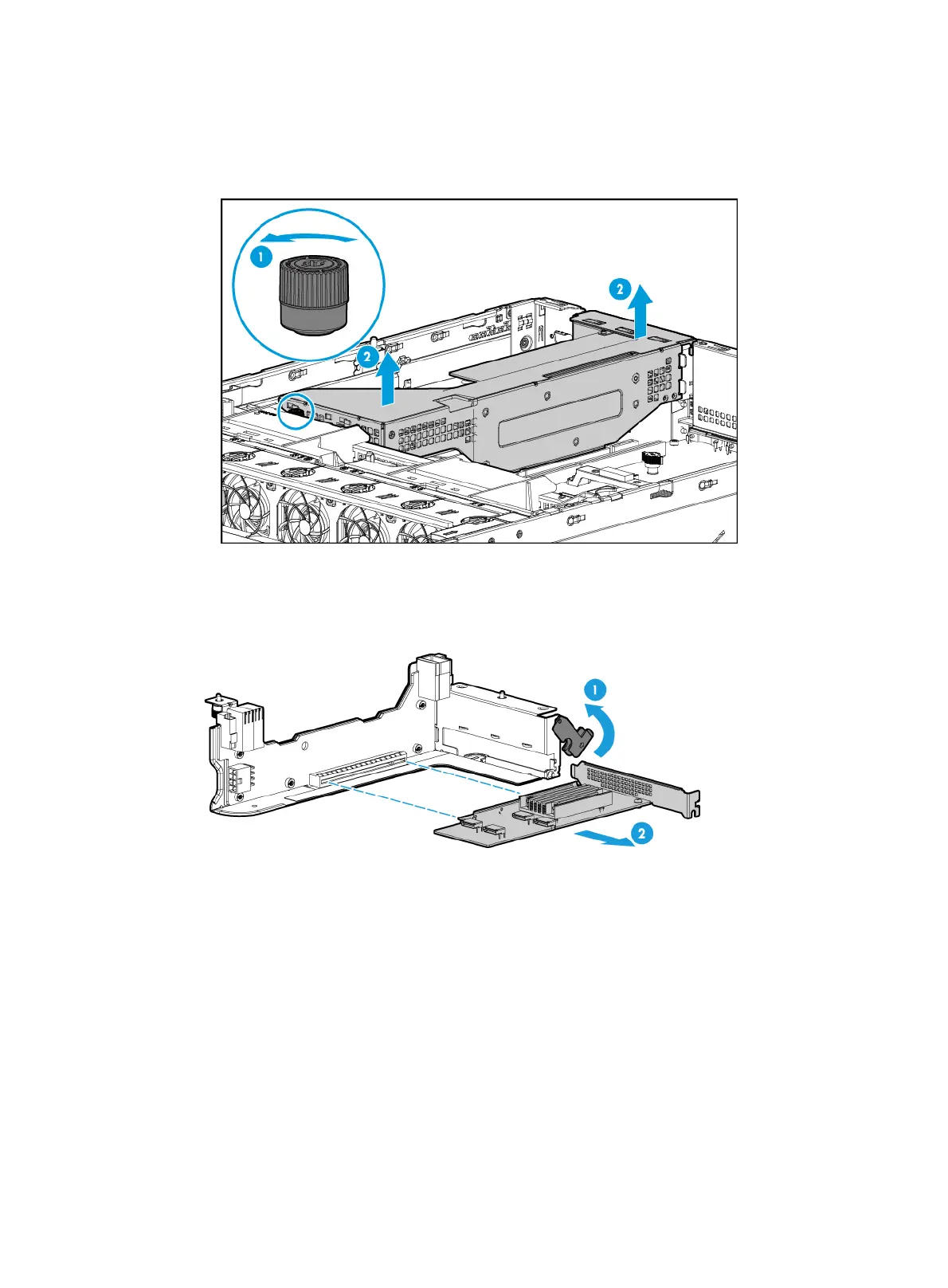
b. Loosen the captive screw on the riser card, and lift the riser card slowly out of the compute
module, as shown in Figure 7-21.
Figure 7-21
Removing the RS-FHHL-G3 riser card
6. Hold and rotate the latch upward to unlock the riser card, and then pull the PCIe module out of
the slot, as shown in Figure 7-22.
Figure 7-22
Removing a PCIe module
7. Install a new riser card and PCIe module. For more information, see "Installing riser cards and
PCIe modules."
8. Install the compute module access panel. For more information, see "Replacing a compute
module a
ccess panel."
9. Install the compute module. For more information, see "Installing a compute module."
10. Install the removed security bezel. For more information, see "Installing the security bezel."
11. Connect the power cord. For more information, see "Connecting the power cord."
12. Powe
r on the server. For more information, see "Powering on the server."
Replacing a riser card and PCIe module at the server rear
The procedure is the same for all the riser cards at the server rear. This section uses the
RS-6*FHHL-G3-1 riser card as an example.

 Loading...


