10-4
Item Description
(14) Riser card air baffle
Provides ventilation aisles for PCIe modules in riser cards at the server
rear.
(15) Chassis N/A
(16) Chassis ears
Attach the server to the rack. The right ear is integrated with the front I/O
component, and the left ear is integrated with VGA and USB 2.0
connectors. The serial label pull tab on the left ear provides the HDM
default login settings and document QR code.
(17) LCD
The LCD is not supported currently.
Displays basic server information and operating status, and allows users
to perform basic server settings.
(18) Diagnostic panel Displays information about faulty components for quick diagnosis.
(19) Drive Drive for data storage.
(20) Drive backplane Provides power and data channels for drives.
(21) Right air baffle
Provides ventilation aisles for processor heatsinks and DIMMs, and an
installation location for a supercapacitor.
(22) Compute module and its
main board
Integrates all compute module parts and components.
(23) Supercapacitor
Supplies power to the flash card of the power fail safeguard module,
which enables the storage controller to back up data to the flash card for
protection when power outage occurs.
(24) Supercapacitor holder Secures a supercapacitor in the chassis.
(25) Memory Stores computing data and data exchanged with external storage.
(26) Low mid air baffle
Used in a compute module when the RS-FHHL-G3 riser card is installed
to provide ventilation aisles for DIMMs.
(27) Riser card 0 Installed on the PCIe riser connector in a compute module.
(28) Processor
Integrates a memory processing unit and a PCIe controller to provide
data processing capabilities for the server.
(29) Processor retaining bracket Attaches a processor to the heatsink.
(30) Processor heatsink Cools the processor.
(31) Compute module access
panel
N/A
Front panel
Front panel view of the server
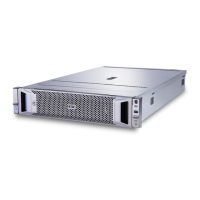
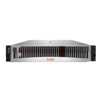
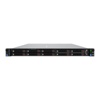
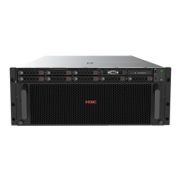
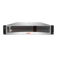
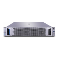
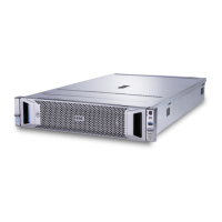
Figure 10-3, Figure 10-4, and Figure 10-5 show the front panel views of 48SFF, 32SFF, and 16SFF
servers, respectively.
 Loading...
