Chapter 6: Receiver Configuration Modules Satellite Receiver Configuration
© Harmonic Inc. Manual p/n 101543/Ver 1.0 6-24 ProView 2900 Series/SW Version 1.94
6.2.3.6. Spectral Inversion
The Spectral Inversion parameter sets the spectral mode of operation. This parameter is
configured according to the information provided from the broadcast head-end or can be set
to automatic. When set to automatic mode, the ProView 2900 tries the two spectral modes
until obtaining synchronization.
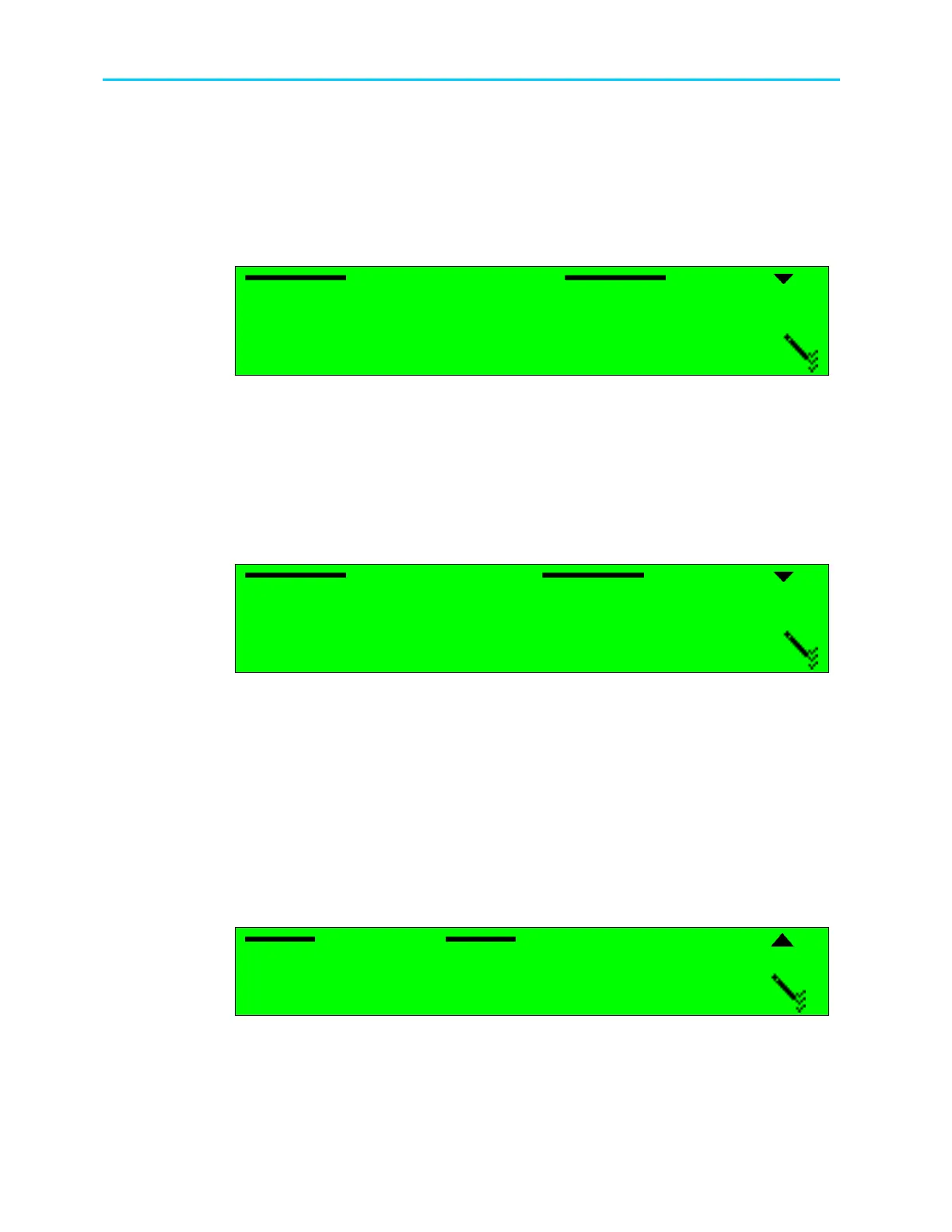
The following figure illustrates the Spectral Inversion screen.
Spectral Inversion
Spectral Inversion Spectral Inversion
Spectral Inversion
1
11
1
AUTOMATIC
AUTOMATIC AUTOMATIC
AUTOMATIC
2
22
2
INVERTED
INVERTED INVERTED
INVERTED
3
33
3
NORMAL
NORMAL NORMAL
NORMAL
The available options are: AUTOMATIC, INVERTED or NORMAL spectral mode.
6.2.3.7. LNB Power Supply
The ProView 2900 sets the polarization of the receiving antenna by providing different
voltage levels to the satellite Low Noise Block (LNB), 13v for vertical polarization and 18v for
horizontal polarization. The polarization of the receiving antenna is determined according to
the polarity of the satellite transponder.
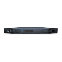
The following figure illustrates the LBN Power Supply screen.
LNB Power Supply
LNB Power Supply LNB Power Supply
LNB Power Supply
1
11
1
13V (VERTICAL)
13V (VERTICAL) 13V (VERTICAL)
13V (VERTICAL)
2
22
2
18V (HORIZONTAL)
18V (HORIZONTAL) 18V (HORIZONTAL)
18V (HORIZONTAL)
3
33
3
OFF
OFF OFF
OFF
The available options are:
• 13V (VERTICAL) – sets the LNB polarization to vertical.
• 18V (HORIZONTAL) - sets the LNB polarization to horizontal.
• OFF –power to the LNB is disabled.
6.2.3.8. LNB 22KHz
The receiver controls the LNB band by sending a 22 kHz signal. When the signal is sent, the
LNB uses its High Band Local Oscillator (L.O.). When the signal is not sent, the LNB uses its
own Low Band L.O. The local oscillator is used to convert the signal from Ku-Band or C-Band
to L-Band. Two local oscillators exist; one for each band to leverage full spectrum. The
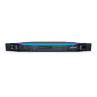
following figure illustrates the LNB 22KHz screen.
LNB 22 KHz
LNB 22 KHz LNB 22 KHz
LNB 22 KHz
1
11
1
OFF (Low Band)
OFF (Low Band) OFF (Low Band)
OFF (Low Band)
2
22
2
ON (High Band)
ON (High Band) ON (High Band)
ON (High Band)
The available options are:
• OFF (Low Band) – the 22 kHz signal is not generated and low band reception is
selected.
• ON (High Band) - the 22 kHz signal is generated and high band reception is selected.