Chapter 5: Operation and Management ProView 2900 Status Menu
© Harmonic Inc. Manual p/n 101543/Ver 1.0 5-16 ProView 2900 Series/SW Version 1.94
5.4.1.3. DSNG Receiver Status
To access the DVB-S2 Receiver status screen in front panel control interface go to
Status
Receiver.
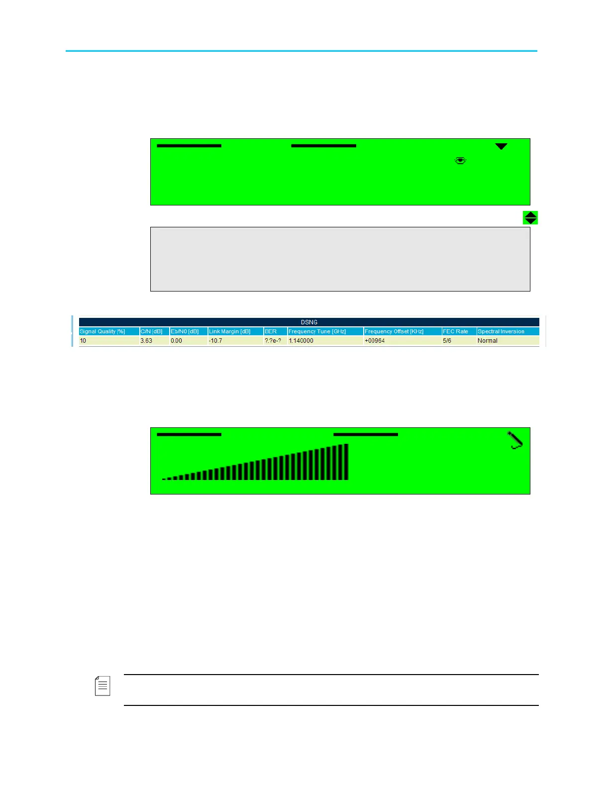
The following screen displays the DVB-S2 Receiver status menu:
Receiver
Receiver Receiver
Receiver
1
11
1-
--
-3
33
3-
--
-1
11
1
1 Signal Quality
1 Signal Quality1 Signal Quality
1 Signal Quality
100[%]
100[%]100[%]
100[%]
2
2 2
2 C/N
C/NC/N
C/N
1
11
19.
9.9.
9.69
6969
69[dB]
[dB][dB]
[dB]
3 Eb/N0
3 Eb/N03 Eb/N0
3 Eb/N0
09.94[dB]
09.94[dB]09.94[dB]
09.94[dB]
4
44
4 Link Margin
Link Margin Link Margin
Link Margin
+04.9
+04.9+04.9
+04.9[
[[
[dB]
dB]dB]
dB]
5 BER
5 BER5 BER
5 BER
0.0e
0.0e0.0e
0.0e-
--
-7
77
7
6 Frequency
6 Frequency 6 Frequency
6 Frequency Tune
TuneTune
Tune
1.068000
1.0680001.068000
1.068000[
[[
[G
GG
GHz]
Hz]Hz]
Hz]
7
7 7
7 Frequency Offset
Frequency OffsetFrequency Offset
Frequency Offset
+02214[KHz]
+02214[KHz]+02214[KHz]
+02214[KHz]
8
88
8
FEC
FECFEC
FEC Rate
Rate Rate
Rate
5/6
5/65/6
5/6
9
99
9 Spectral Inversion
Spectral Inversion Spectral Inversion
Spectral Inversion
NORMAL
NORMALNORMAL
NORMAL
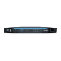
Figure 5-6 displays the corresponding DSNG Status Web management screen.
Figure 5-6: ProView 2900 DSNG Receiver Status Screen
The available options are:
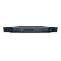
• Signal Quality – Qualitative indicator of the received signal C/N relative to the maximum
C/N that can be measured without forcing the receiver to saturation.
The signal quality is calculated by: SQ[%]=C/N [dB]/36 *100
Signal Quality
Signal Quality Signal Quality
Signal Quality
100 [%]
100 [%]100 [%]
100 [%]
< 000
< 000 < 000
< 000 -
--
- 100 >
100 > 100 >
100 >
• C/N – Shows the Carrier to Noise ratio.
• Eb/N0 – Received signal Eb/N0 measurement
• Link Margin – Estimated C/N of the received signal relative to the C/N in EN 300-421 for
a given FEC rate
• BER – Uncorrected FEC bits errors. BER is measured over 10
7
symbols.
• Frequency Tune – The value is dependent on the mode selected in
Root
Configuration
Receiver
Freq Drift Compensation (see Section 6.2).
• When Frequency Drift Compensation is set On, the value of the frequency
tune displays the frequency of the incoming signal after frequency offset is set
Off.
• When Frequency Drift Compensation is set Off, the value of the frequency
tune displays the actual frequency.
NOTE
Displayed frequencies are L-Band frequencies.