Global Functions
DML-1200 w/Axon Embedded Graphic Engine 24/12/2010 _____________________________________________________________________________ 52
Adjusting the Spherical Mapping effect requires a total of nine modifier parameters. In addition to the three Global Effects Modifier
parameters associated with the Spherical Mapping selection, six modifier parameters are accessed by setting any Global or Graphic
Effect Mode parameters to a DMX value of 253 or 254. Any available effect mode from any Graphic Object can be used. The Effects
Mode parameters used do not have to be from the same Graphic Object. One of these parameters enables the Effects Mode
Modifiers to control the vertical position of the projector (actually the graphics viewpoint), the vertical position of the sphere and
a vertical size. The other Effect Mode selection provides Modifier parameters to control the amount of vertical bend in horizontal
lines, the vertical center of the added bend, and horizontal size.
4.12.5.1 Spherical Mapping Setup Guide
Before You Begin
Successful spherical mapping requires careful positioning of the DML-1200 w/Axon fixture. Units should be mounted at equal
angles from each other and the same distance from the sphere. Mounting units at the same height will minimize the tilt angle
adjustments you will need to make.
Mapping Two Outputs to a Sphere
The following example describes mapping two outputs on a sphere, with each covering half of the surface. For best results, make
each adjustment to both outputs as you follow the example. After you’ve completed the following steps, you can more easily
transfer the DMX values to the outputs for other cells of the Collage.
Select a Global Effect and two Graphic Effects to control Spherical Mapping:
1. Set
Global Effect
channel to a DMX value = 142 to select the Spherical Mapping option. Set the three associated
Global Effect
Modifier
parameters
to their default values (Modifier 1=0, Modifier 2=0, Modifier 3 = 128).
2. Select the Spherical Mapping Control 1 option (DMX = 253) in any available Graphic
Effect Mode
channel. Set the three
associated Effect Modifiers to their default DMX values (Modifier 1 = 128, Modifier 2 = 128, Modifier 3 = 64).
3. Select the Spherical Mapping Control 2 option (DMX value = 254) on any available
Graphic
Effect Mode
channel. Set all
associated Effect Modifiers to their default DMX values. (Modifier 1 = 0, Modifier 2 = 128, Modifier 3 = 64)
4. In the
Global Control
channel, select the on-screen statistics for the spherical mapping option (DMX value = 252). Use the
Global Control Modifier
to select text color for easier viewing.
5. Select the 4 x 3 (Flat Plane) option in the
3-D Object
channel (DMX = 1).
6. Select the HES Set Up and Test option in the
Media Folder
channel (DMX = 39), and Test Grid.jpg in the
File Folder
(DMX = 9).
At this point, you should be viewing the two projected grids with statistics displayed. If
you do not see an output, check that all Modifier parameters are set to their default
values. Before you begin other adjustments, physically view the grid from along the
center line of the fixture. The center line of the grid should align with the center of the
sphere. You can easily adjust any variation using the Pan channel. The object is to align
the vertical lines of the guide with the vertical axis of the sphere.
Adjust output positioning on the sphere:
7. Use
Global Effect Modifier 2
to adjust the latitude angle. You can view the Latitude
top and Latitude bottom statistics to see the degrees of spread + or – from the
“equator”.
8. Use
Global Effect Modifiers 3
to move the output up or down to the part of the
sphere you want to cover. The Latitude top and Latitude bottom statistics show you
the center of adjustment in degrees + or – from the “equator”.
9. Adjust the
Global Effect Modifier 1
to set the longitude angle.
Make viewpoint adjustments:
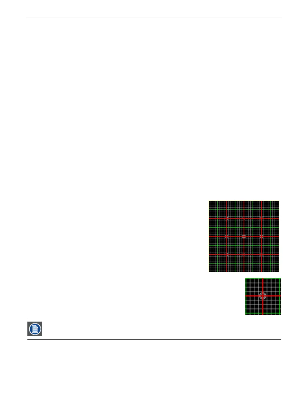
10. On the
Graphic Effect Mode
channel set to Spherical Control 1 (DMX = 253), use
Modifier 1
to
move the
center of the grid to the center of the output marked by the double circles around the crossed lines. This
adjusts vertical offset to accommodate the projector’s position. The default value assumes a viewpoint
straight on to the “equator”.
Modifier 2
adjusts the sphere’s offset to compensate for projector head tilt.
11. Use
Modifier 3
to adjust the vertical size of the output, stretching and compressing it to adjust for the size of the sphere,
keeping the vertical size of the grid filling the output without clipping the image.
After completing a rough adjustment, you will use these two modifier channels for the fine tuning.