Page Display Definitions
2-27
GNS-XLS Flight Management System
Rev. 5
Sep/97
NOTE: Entering 99 in this field will eliminate any previously entered
value and no CHECK QUALITY message will appear.
CURRENT MODE: Indicates the current mode of VPU navigation.
The messages that can appear under it: (Figure 2-32)
• NO MEASUREMENTS indicates that VPU is not receiving valid
data for navigation.
• VOR/DME indicates that distance and bearing (rho/theta) informa-
tion is used to generate VPU position.
• DME/DME indicates distance (rho/rho) data is received and used
to generate VPU position.
• BAD GEOMETRY indicates that station geometry is inadequate for
navigation.
NAV 1 - CONFLICT or NAV 2 - CONFLICT:
The VPU is not using a manually or keyboard tuned station because
of a possible station frequency conflict within the aircraft’s current
line-of-sight. (Figure 2-32)
VPU SUBSECTION 3/4 (Page 3 of 4)
Pressing the NXT Key again will display the third VPU SUBSECTION
Page and the following can be observed.
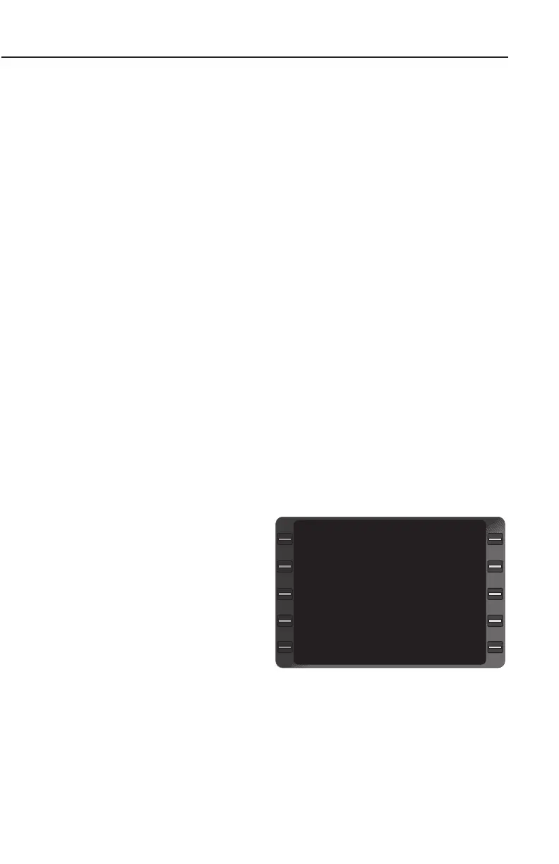
VPU Sensor With Single Channel DME Inputs (Figure 2-33)
NAV 1 and NAV 2:
The station identifier and fre-
quency being used for navi-
gation.
RNG:
The range in nautical miles
and tenths from aircraft pre-
sent position to the DME sta-
tion.
BRG:
Bearing in whole degrees from aircraft present position to the VOR.
VPU STATIONS
NAV 1 PRX 113.60
RNG 51.2
BRG 304
NAV 2 UIM 114.00
RNG 34.7
BRG 252
VPU SUBSECTION 3/4
Figure 2-33
 Loading...