System Address Map
R
158 Intel
®
82925X/82925XE MCH Datasheet
The rules for the above programmable ranges are:
• ALL of these ranges MUST be unique and NON-OVERLAPPING. It is the BIOS or system
designer’s responsibility to limit memory population so that adequate PCI, PCI Express, High
BIOS, PCI Express Memory Mapped space, and APIC memory space can be allocated.
• In the case of overlapping ranges with memory, the memory decode will be given priority.
• There are NO Hardware Interlocks to prevent problems in the case of overlapping ranges.
• Accesses to overlapped ranges may produce indeterminate results.
• The only peer-to-peer cycles allowed below the top of memory (register TOLUD) are DMI to
PCI Express VGA range writes.
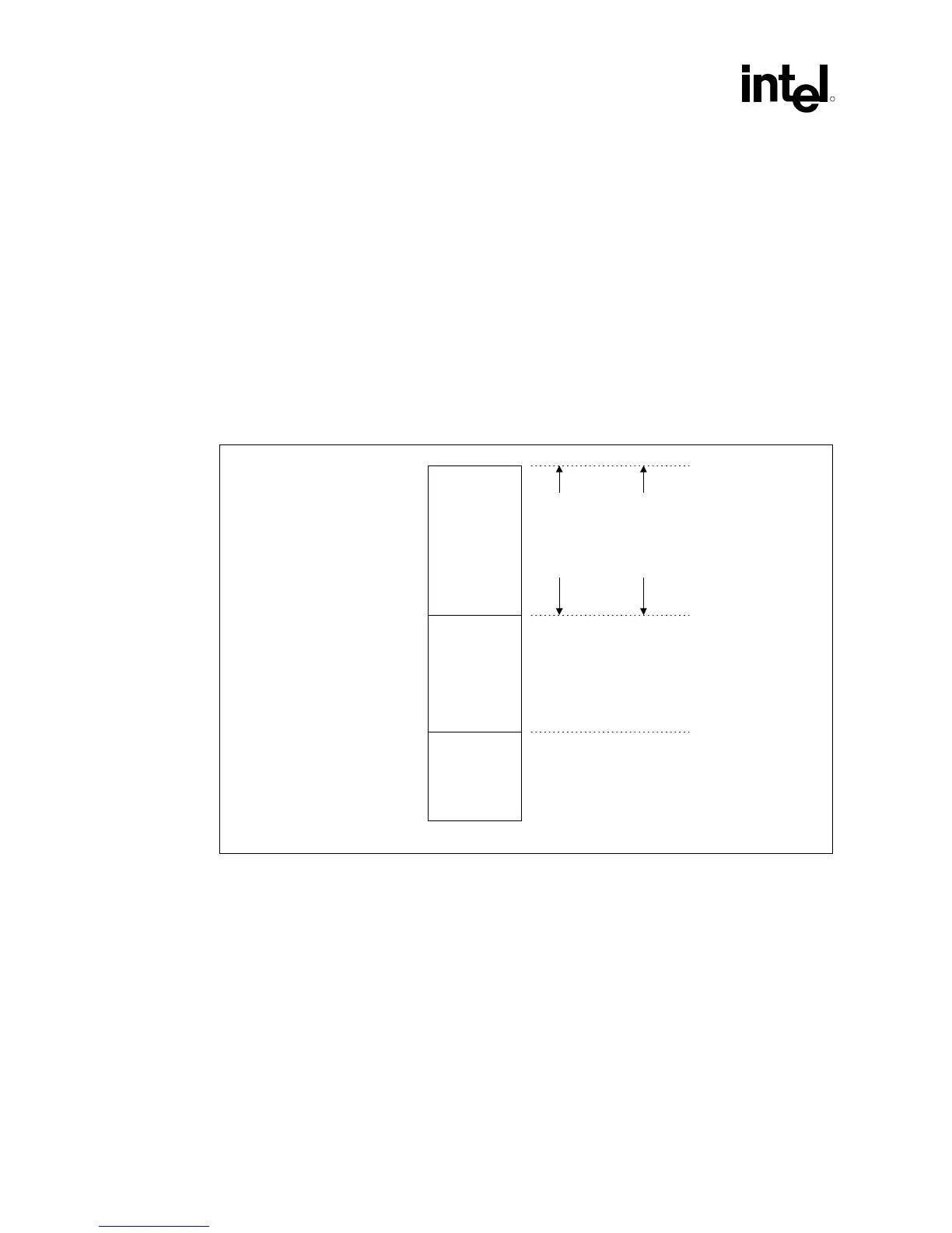
Figure 9-1 shows the system memory address map in a simplified form.
Figure 9-1. System Address Ranges
PCI Memory
Address Range
(Subtractively
decoded to DMI)
Main Memory
Address Range
Legacy Address
Range
0
1 MB
TOLUD
4 GB
Device 0
Bars
(EPBAR,
MCHBAR,
PCIEXBAR,
DMIBAR)
Device 1
Bars
(MBASE1/
MLIMIT1,
PMBASE1/
PMLIMIT1)
Independently Programmable
Non-Overlapping Windows
Sys_Address_Ranges
9.1 Legacy Address Range
This area is divided into the following address regions:
• 0 – 640 KB: DOS Area
• 640 – 768 KB: Legacy Video Buffer Area
• 768 – 896 KB in 16-KB sections (total of 8 sections): Expansion Area
• 896 – 960 KB in 16-KB sections (total of 4 sections): Extended System BIOS Area
• 960-KB – 1-MB Memory: System BIOS Area
 Loading...


