MCHBAR Registers
R
80 Intel
®
82925X/82925XE MCH Datasheet
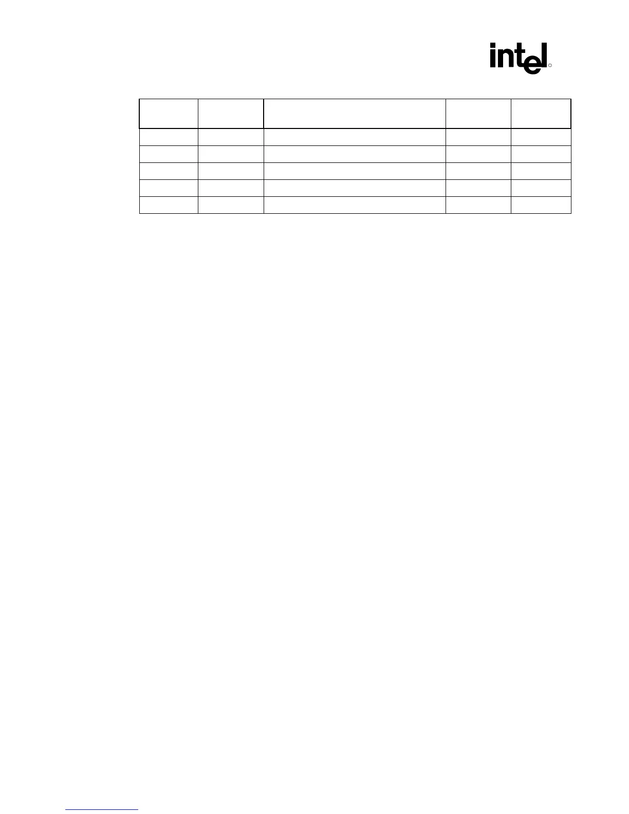
Address
Offset
Register
Symbol
Register Name
Default
Value
Access
195–19Fh — Reserved — —
1A0–1A3h C1DRC0 Channel B DRAM Controller Mode 0 00000000h R/W, RO
1A4–F0Fh — Reserved — —
F10–F13h PMCFG Power Management Configuration 00000000h R/W
F14h PMSTS Power Management Status 00000000h R/W/C/S
5.1 MCHBAR Register Details
5.1.1 C0DRB0—Channel A DRAM Rank Boundary Address 0
MMIO Range: MCHBAR
Address Offset: 100h
Default Value: 00h
Access: R/W
Size: 8 bits
The DRAM Rank Boundary Register defines the upper boundary address of each DRAM rank
with a granularity of 32 MB. Each rank has its own single-byte DRB register. These registers are
used to determine which chip select will be active for a given address.
Channel and Rank Map:
Channel A Rank 0: 100h
Channel A Rank 1: 101h
Channel A Rank 2: 102h
Channel A Rank 3: 103h
Channel B Rank 0: 180h
Channel B Rank 1: 181h
Channel B Rank 2: 182h
Channel B Rank 3: 183h
Single Channel or Asymmetric Channels Example
If the channels are independent, addresses in Channel B should begin where addresses in Channel
A left off, and the address of the first rank of Channel A can be calculated from the technology
(256 Mbit, 512 Mbit, or 1 Gbit) and the x8 or x16 configuration. With independent channels, a
value of 01h in C0DRB0 indicates that 32 MB of DRAM has been populated in the first rank, and
the top address in that rank is 32 MB.
 Loading...


