Signal Description
R
28 Intel
®
82925X/82925XE MCH Datasheet
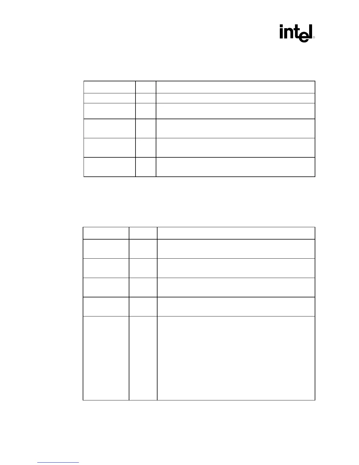
2.4 DDR2 DRAM Reference and Compensation
Signal Name Type Description
SRCOMP[1:0] I/O System Memory RCOMP
SOCOMP[1:0] I/O
A
DDR2 On-Die DRAM Over Current Detection (OCD) driver
compensation
SM_SLEWIN[1:0] I
A
Buffer Slew Rate Input: Slew Rate Characterization buffer input for X
and Y orientation.
SM_SLEWOUT[1:0] O
A
Buffer Slew Rate Output: Slew Rate Characterization buffer output for
X and Y orientation
SMVREF[1:0] I
A
SDRAM Reference Voltage: Reference voltage inputs for each DQ,
DM, DQS, and DQS# input signals.
2.5 PCI Express* x16 Graphics Port Signals
Unless otherwise specified, PCI Express Graphics signals are AC coupled, so the only voltage
specified is a maximum 1.2 V differential swing.
Signal Name Type Description
EXP_RXN[15:0]
EXP_RXP[15:0]
I/O
PCIE
PCI Express Graphics Receive Differential Pair
EXP_TXN[15:0]
EXP_TXP[15:0]
O
PCIE
PCI Express Graphics Transmit Differential Pair
EXP_COMPO I
A
PCI Express Graphics Output Current Compensation
Note: EXP_COMP0 is used for DMI current compensation.
EXP_COMPI I
A
PCI Express Graphics Input Current Compensation
Note: EXP_COMPI is used for DMI current compensation.
EXP_SLR I
CMOS
PCI Express* Static Lane Reversal: The MCH’s PCI Express lane
numbers are reversed. For example, the MCH PCI Express interface
signals can be configured as follows:
Normal Lane
Ball Operation Reversed
C10 EXP_TXP0 EXP_TXP15
A9 EXP_TXP1 EXP_TXP14
… … …
N3 EXP_TXP14… EXP_TXP1…
P1 EXP_TXP15 EXP_TXP0
0 = MCH’s PCI Express lane numbers are reversed
1 = Normal operation
 Loading...


