members of the VLAN receive traffic from the same VLAN members. The screen in Figure 4-6-8 appears
and Table 4-6-9 describes the port configuration of the Managed Switches.
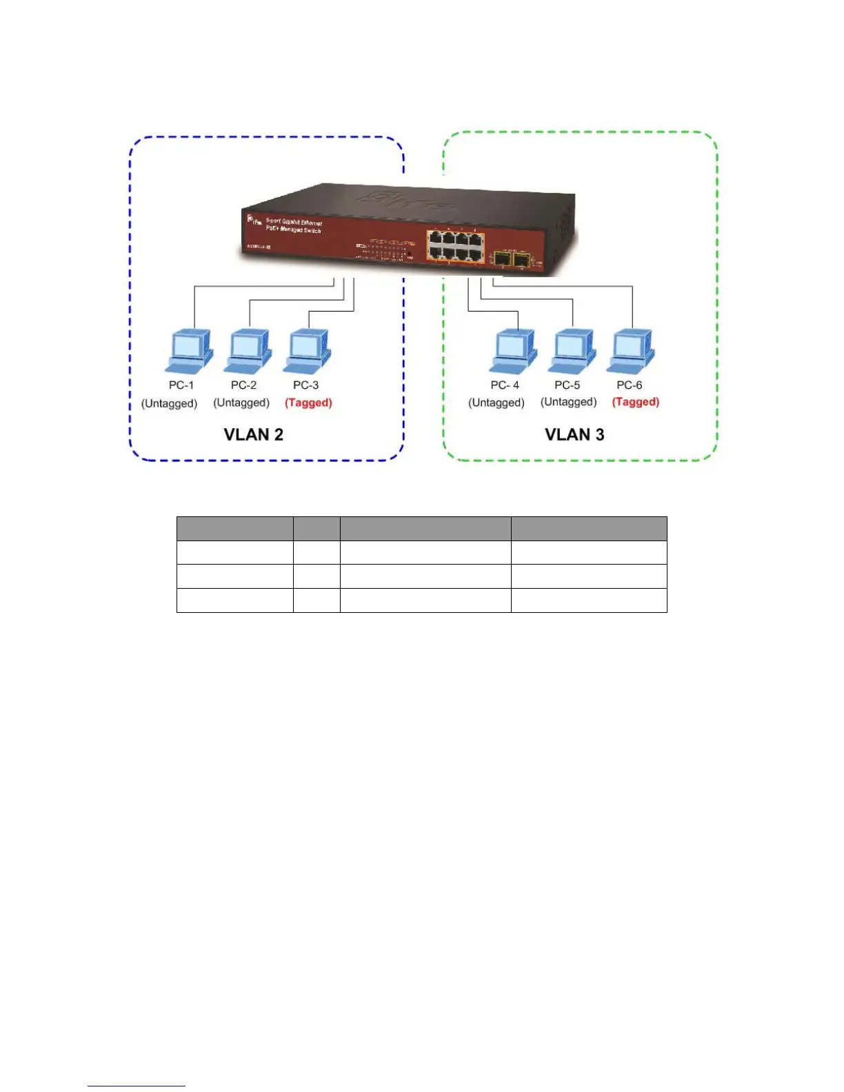
Figure 4-6-8: two separate VLAN diagram
VLAN Group VID Untagged Members Tagged Members
VLAN Group 1 1 Port-7 ~ Port-10 N/A
VLAN Group 2 2 Port-1,Port-2 Port-3
VLAN Group 3 3 Port-4,Port-5 Port-6
Table 4-1: VLAN and Port Configuration
The scenario described as follow:
Untagged packet entering VLAN 2
1. While [PC-1] transmit an untagged packet enters Port-1, the Managed Switch will tag it with
a VLAN Tag=2. [PC-2] and [PC-3] will received the packet through Port-2 and Port-3.
2. [PC-4], [PC-5] and [PC-6] received no packet.
3. While the packet leaves Port-2, it will be stripped away on tag becoming an untagged packet.
4. While the packet leaves Port-3, it will keep it as a tagged packet with VLAN Tag=2.
Tagged packet entering VLAN 2
5. While [PC-3] transmit a tagged packet with VLAN Tag=2 enters Port-3, [PC-1] and [PC-2] will
received the packet through Port-1 and Port-2.
6. While the packet leaves Port-1 and Port-2, it will be stripped away on a tag becoming an
untagged packet.
 Loading...