4. Assign the VLAN Trunk Port to be the member of each VLAN – which wants to be aggregated. At
this sample, add Port-8 to be VLAN 2 and VLAN 3 member port. The screen in Figure 4-6-12
appears.
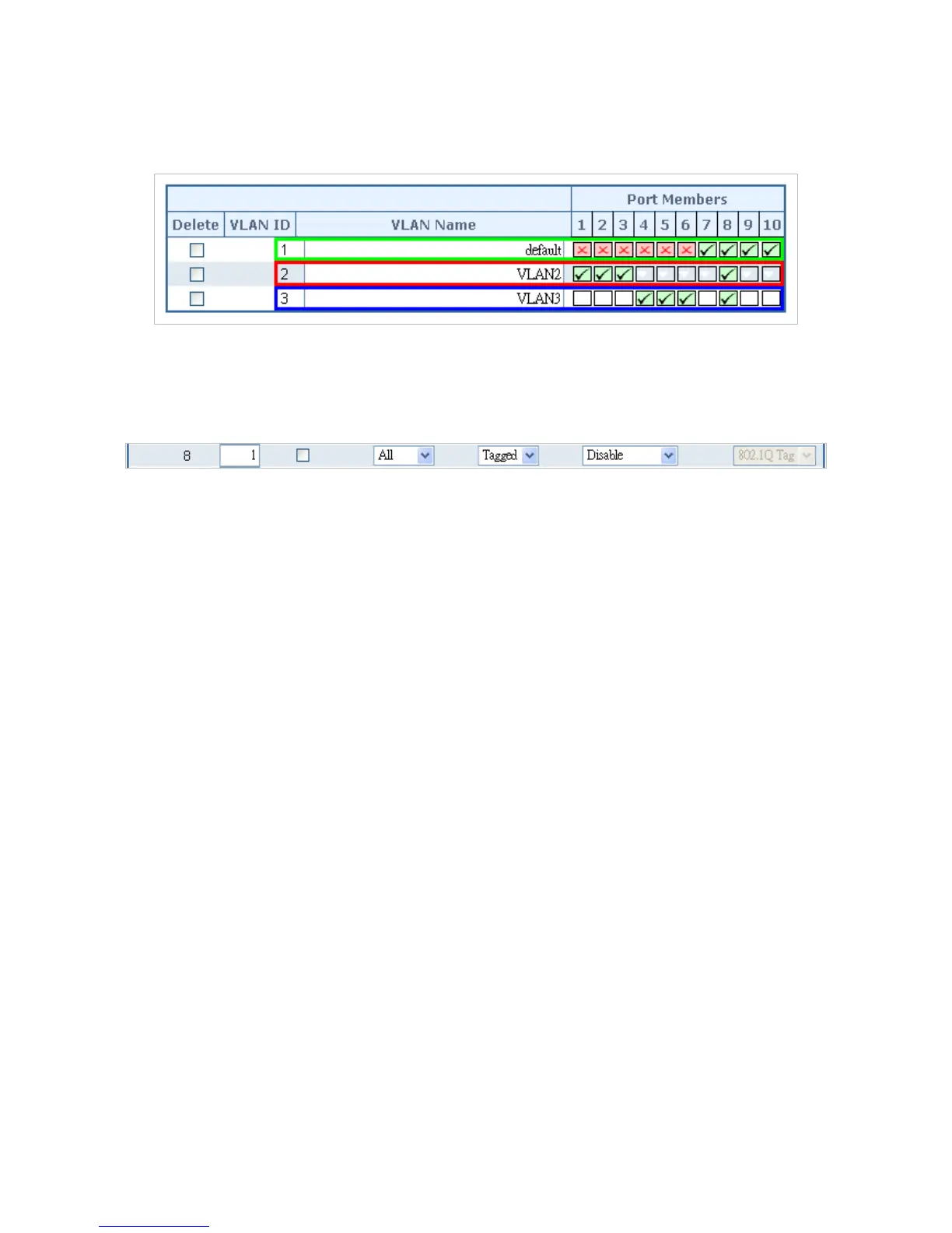
Figure 4-6-12: VLAN overlap port setting & VLAN 1 – The public area member assign
5. Specify Port-8 to be the 802.1Q VLAN Trunk port, and the Trunking port must be a Tagged port
while egress. The Port-8 configuration as the following screen in Figure 4-6-13.
Figure 4-6-13: The configuration of VLAN Trunk port
That is, although the VLAN 2 members: Port-1 to Port-3 and VLAN 3 members: Port-4 to Port-6 also
belongs to VLAN 1. But with different PVID settings, packets form VLAN 2 or VLAN 3 is not able to
access to the other VLAN.
6. Repeat Step 1 to 5, setup the VLAN Trunk port at the partner switch and add more VLANs to join
the VLAN trunk, repeat Step 1 to 3 to assign the Trunk port to the VLANs.
4.6.10.3 Port Isolate
The diagram shows how the Managed Switch handles isolate and promiscuous ports and the each PC
are not able to access each other PCs of each isolate port. But they all need to access with the same
server/AP/Printer. The screen in Figure 4-6-14 appears. This section will show you how to configure the
port for the server – that could be accessed by each isolate port.
 Loading...