Lights to indicate the port is providing 52VDC in-line power
Off: indicate the connected device is not a PoE Powered Device (PD)
1000
LNK/ACT
Green
Lights to indicate the port is running in 10/100Mbps speed and
successfully established.
Blink: indicate that the switch is actively sending or receiving data over
Per 100/1000Base-X SFP interfaces
LED Color Function
1000 Green
Lights to indicate the link through that port is successfully established.
Blink: indicate that the switch is actively sending or receiving data over
that port.
100 Green
Lights to indicate the link through that port is successfully established.
Blink: indicate that the switch is actively sending or receiving data over
that port.
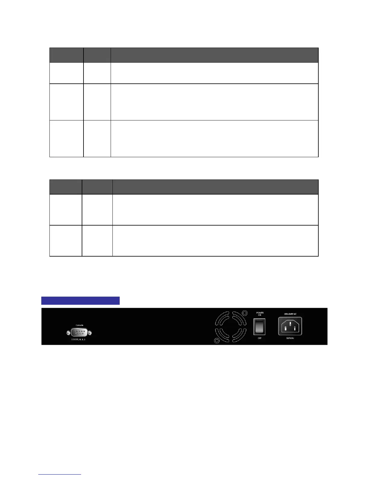
2.1.3 Switch Rear Panel
The rear panel of the Managed Switch indicates an AC inlet power socket, which accepts input
power from 100 to 240V AC, 50-60Hz. Figure 2-3 shows the rear panel of these Managed Switches
NS3502-8P-2S Rear Panel
Figure 2-3: Rear panel of NS3502-8P-2S
■ AC Power Receptacle
For compatibility with electric service in most areas of the world, the Managed Switch’s power
supply automatically adjusts to line power in the range 100-240VAC and 50/60 Hz.
Plug the female end of the power cord firmly into the receptacle on the rear panel of the
Managed Switch. Plug the other end of the power cord into an electric service outlet then the
power will be ready.
 Loading...