Step5: Supply power to the Managed Switch.
Connect one end of the power cable to the Managed Switch.
Connect the power plug of the power cable to a standard wall outlet.
When the Managed Switch receives power, the Power LED should remain solid Green.
2.2.2 Rack Mounting
To install the Managed Switch in a 19-inch standard rack, please follows the instructions described
below.
Step1: Place the Managed Switch on a hard flat surface, with the front panel positioned towards the
front side.
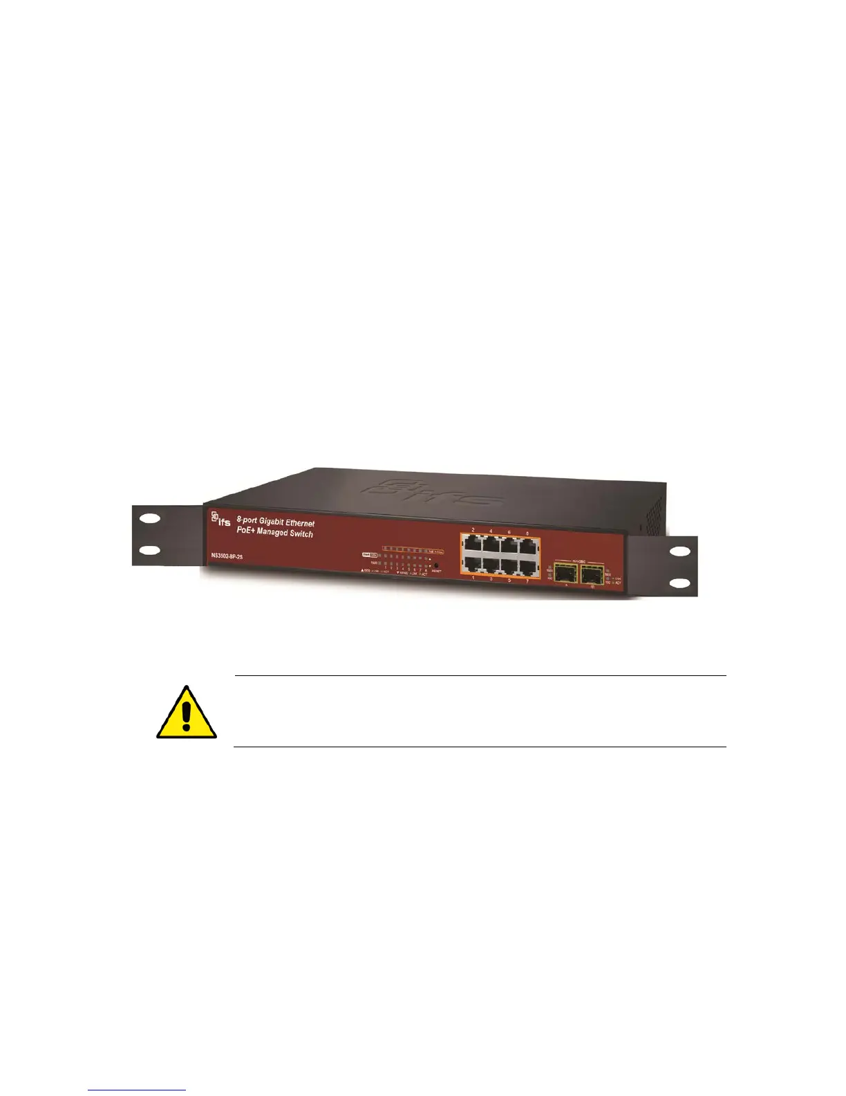
Step2: Attach the rack-mount bracket to each side of the Managed Switch with supplied screws
attached to the package.
Figure 2-5 shows how to attach brackets to one side of the Managed Switch.
Figure 2-5: Attach brackets to the Managed Switch.
You must use the screws supplied with the mounting brackets. Damage
caused to the parts by using incorrect screws would invalidate the warranty.
Step3: Secure the brackets tightly.
Step4: Follow the same steps to attach the second bracket to the opposite side.
Step5: After the brackets are attached to the Managed Switch, use suitable screws to securely
attach the brackets to the rack, as shown in Figure 2-6.
 Loading...