GAPS - User Guide
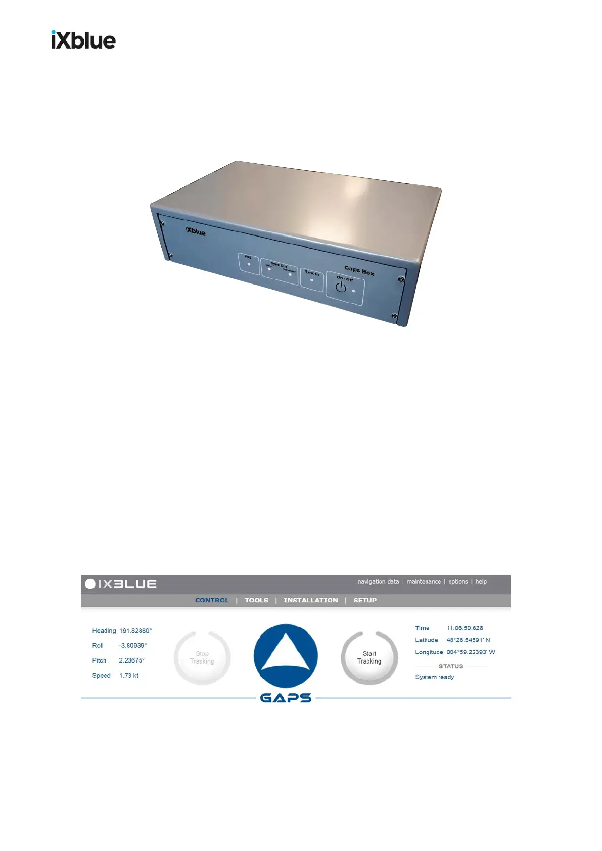
1.2.3 GAPSBOX
The GAPS BOX connects together all the different elements of the system. The GAPS head
and the external sensors (GPS, Synchronization) are directly connected to the BOX. The ship
power supply is provided to the BOX. Ethernet and serial links connectors are available for
data output. The GAPS BOX is necessary to the operation of GAPS.
Figure 4 - GAPS BOX
Connectors
Below are listed the connectors of the GAPS BOX:
● Ethernet: control / command and four input and output links
● Four input and output serial links
● Two synchronization outputs and one synchronization input
● One PPS link
● Power supply VDC / AC
Rack option
On customer request, the GAPS BOX can be rackable (19''rack). See appendix O.
1.2.4 WEB-BASED USERINTERFACE
The Web-based user interface is a web application enabling configuration of the system (lever
arms, management of connections, celerity profile, configuration and management of
transponders) before each mission and checking the data input during the mission. This
application also enables recording of data and the sending of signals for the remote control.
4.1.
Figure 5 - Main window of the Web-based user interface
MU-GAPS-AN-005-H - November 2019 19