GAPS - User Guide
3.3 Installing the GAPS BOX
The connections between the different devices can be set up through the GAPS BOX. Set up
all connections between the different devices of the system. The mechanical drawing of the
BOX is available in Appendix M.
The GAPS BOX is classified as IP 51 (NF EN 60529 2000). The GAPS BOX must be
installed inside the ship. If you have to operate the GAPS BOX on the deck, make sure to use
the appropriate protection for the GAPS BOX.
The exchange of one GAPS BOX by another requires that you reboot the computer on which
runs the Web based User Interface before powering the new GAPS BOX.
3.3.1 ELECTROMAGNETIC COMPATIBILITY RECOMMENDATIONS
GAPS system has been qualified with the following standards:
● EN 60945: 2002
● EN 61000-3-2: 2006 / A1: 2009 / A2: 2009
● EN 61000-3-3: 2008
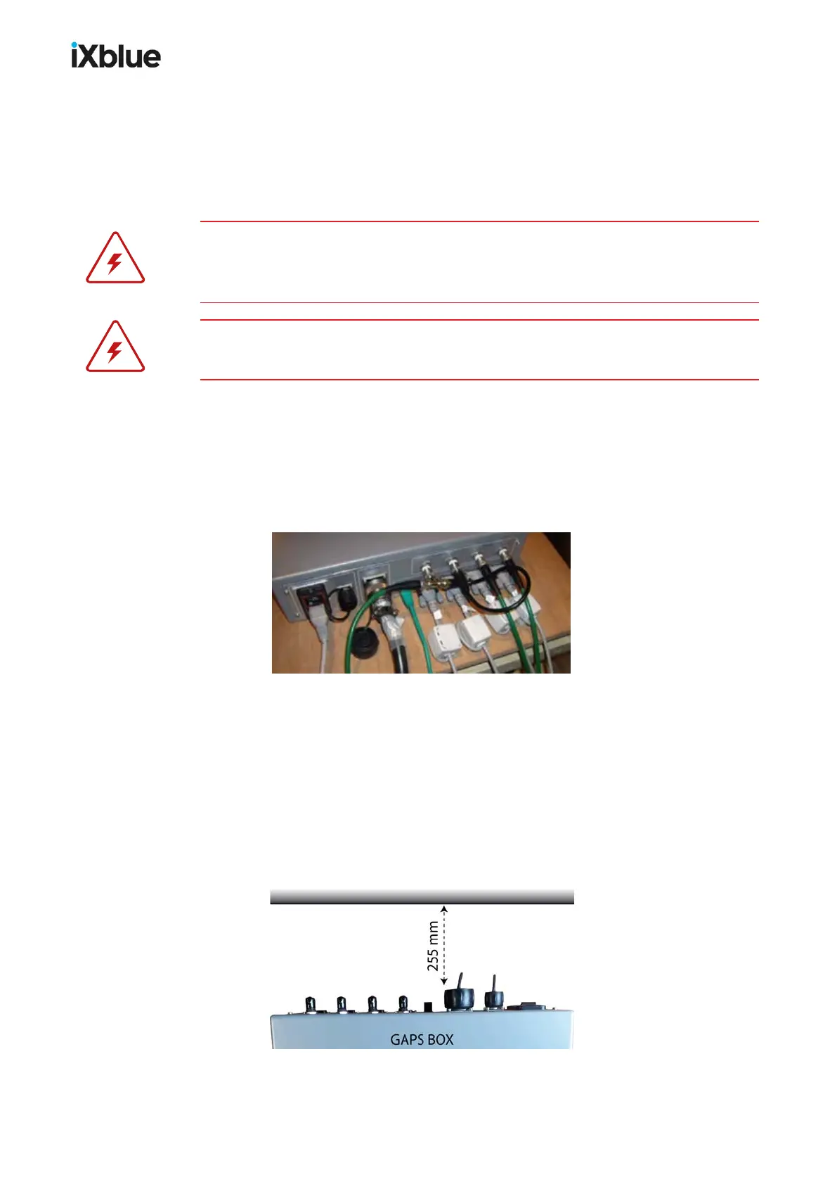
It is recommended to install ferrite cores on the serial cables plugged on to the GAPS BOX.
Figure 21 - Ferrite cores set up on the serial cables of the GAPS BOX
The recommended ferrite cores have the following references:
● WURTH 742 711 12 for Synchro coaxial cables
● WURTH 742 712 21 for serial link cables
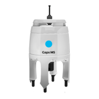
3.3.2 CABLE CURVATURE
As seen in section 2.2.3, the integration of the GAPSBOX must allow a space around the
main connector. This space corresponds to the minimum bending radius (75 mm) of the main
cable and the minimum rigid length (170 mm) of the SOURIAUconnector.
40 MU-GAPS-AN-005-H - November 2019