GAPS - User Guide
1.2.6 OPTIONAL INTEGRATED DGPS
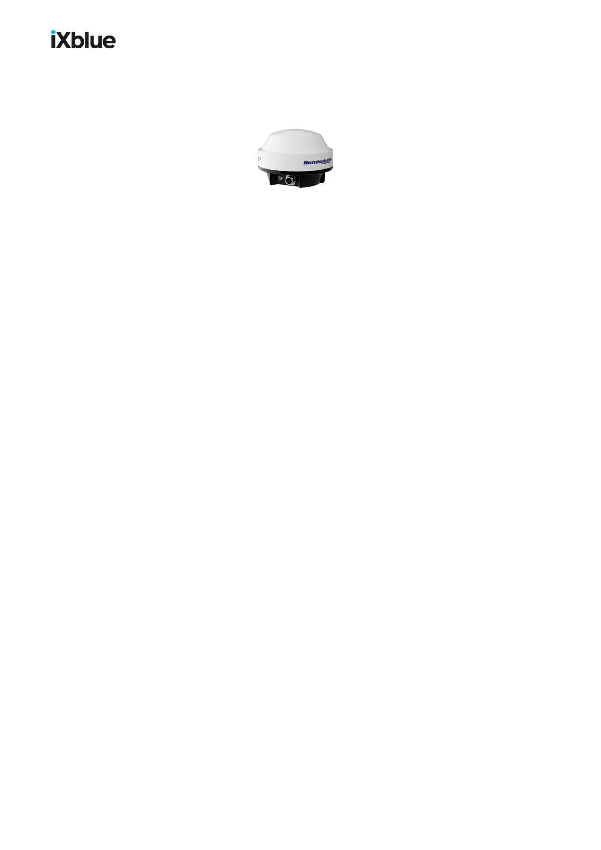
The optional integrated DGPS antenna is compatible with SBAS signals. The MMP26C-
2212S1 connector is IP 67 (resists to immersion at 1 meter during 30 minutes).
Figure 6 - Optional Integrated DGPS
1.2.7 USBL TELEMETRY
GAPS communicates via USBL telemetry with specific transponders (ITSbeacons equipped
with the specific technology, contact iXblue for more details). Data sets are transmitted both
ways in a synchronized way with the acoustic positioning cycles.
Telemetry is carried by the acoustic signals of the ITSbeacons.:
● Interrogation signals MFCHORUSCIS and MFCHORUSIIS
● Reply signals MFCHORUSCRS and MFCHORUSIRS
Typically, the transponder transmits the measurements of its sensors (depth, sound velocity,
etc.) in order to improve the accuracy of the GAPSUSBL positioning.
GAPStransmits orders to the transponder (release, etc.) via the telemetry.
Configuration of the telemetry in input and output is described in section 4.4.1.5
The telemetry datagramuses ITSTELEMETRY (NMEA 183 /$PTLMT) protocol datagram
that is described in appendix H.3.
1.2.8 PING STACKING
The ping stacking mode consists of increasing the positioning rate independently of the slant
range between the USBL antenna and the transponder. The GAPS pings at a faster rate than
usual and does not wait for the detection of the transponder before pinging again.
See section 5.1.5 for a complete description of the ping stacking mode.
1.2.9 OPTIONAL HISYS HOISTING SYSTEM
The GAPS acoustic antenna may be fastened to an iXblue HiSys hoisting system. A
connection between the hoisting system and the GAPS BOX allows the monitoring of the
actual operating states of the hoisting system directly on the Web-based User Interface.
Please refer to HiSys specific user guide for complete operational procedure.
MU-GAPS-AN-005-H - November 2019 21