GAPS - User Guide
10.1.2 CHECKING THE ELECTRICAL GROUND
You must ensure that the electrical installation is correct in order to prevent the antenna from
corrosion. Before proceeding to the test, please make sure that you have:
● Installed the GAPS acoustic antenna
● Installed and powered the BOX
● Connected the cable between the BOX and the acoustic antenna
The test consists in measuring the voltage between the GAPS antenna and the hull of the ship
with a multitester.
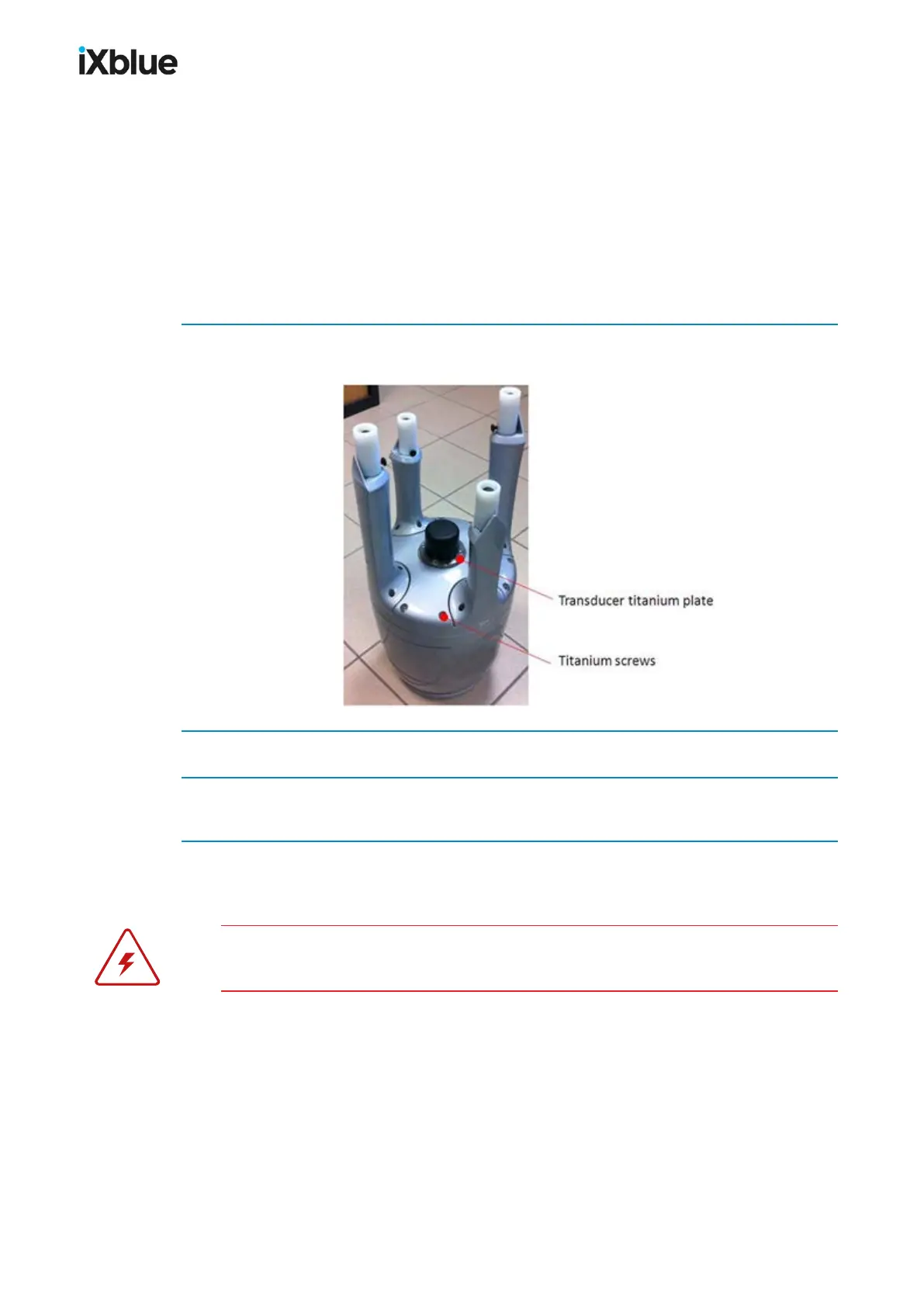
1. Put the first probe of the multitester on a conductive part of the housing of the GAPS antenna.
It can be the transducer titanium plate or the titanium screws.
2. Put the second probe on a conductive part of the ship hull.
3. Read the voltage between these two points.
The voltage must be below 1.0 V.
If the voltage between the GAPS antenna and the hull of the ship is below 1.0 V, the system is
electrically well installed.
If the voltage between the GAPS antenna and the hull of the ship is greater than 1.0 V,
corrosion will impact your system. Contact iXblue technical support.
158 MU-GAPS-AN-005-H - November 2019