EasyManua.ls Logo

Keysight Technologies X Series - Page 487

Keysight Technologies X Series
671 pages
To Next Page IconTo Next Page
To Previous Page IconTo Previous Page
Loading...
Keysight N9010A EXA Service Guide 487
Assembly Replacement Procedures
RF Area (Option 503, 507, 513, 526)
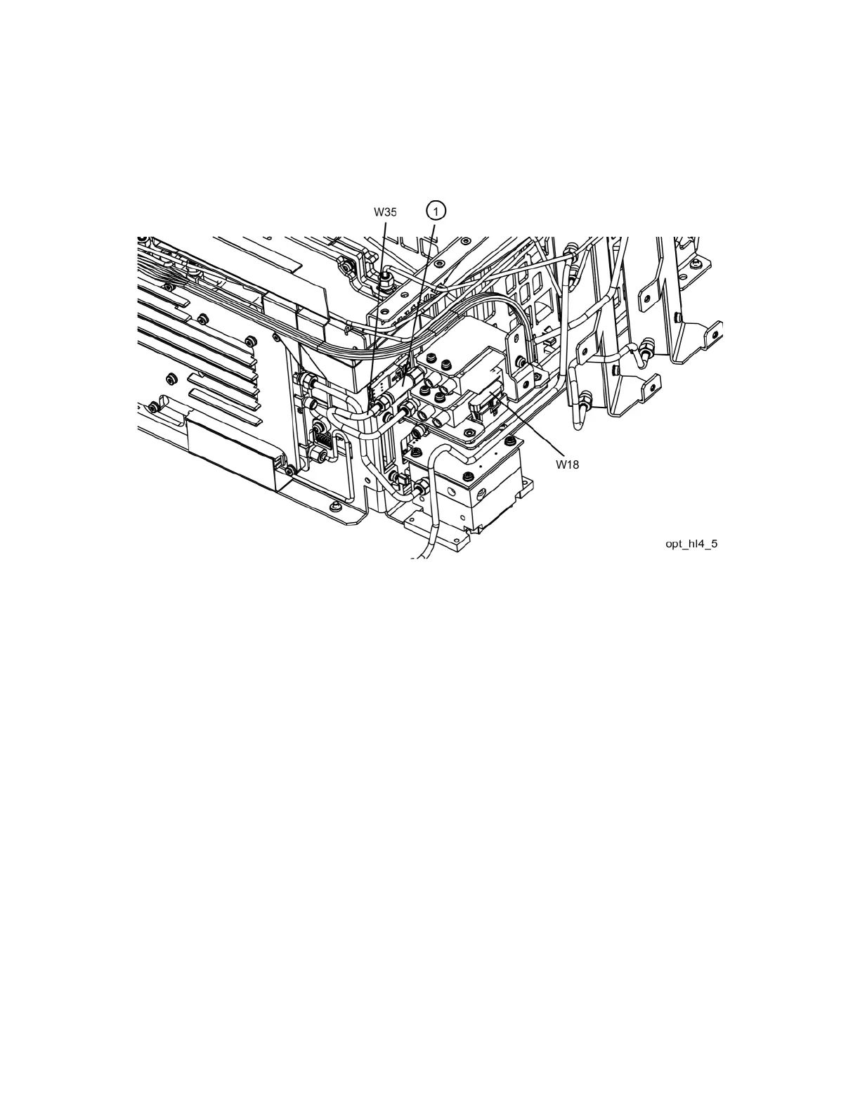
3. Refer to Figure 15-16. Remove semi-rigid coax cable W35 and the fixed
attenuator (1).
Figure 15-16 W35 and Attenuator Removal
4. Remove ribbon cable W18 from J4 of the A11 Low Band Switch.

Table of Contents

Other manuals for Keysight Technologies X Series

Related product manuals