Keysight N9010A EXA Service Guide 489
Assembly Replacement Procedures
RF Area (Option 503, 507, 513, 526)
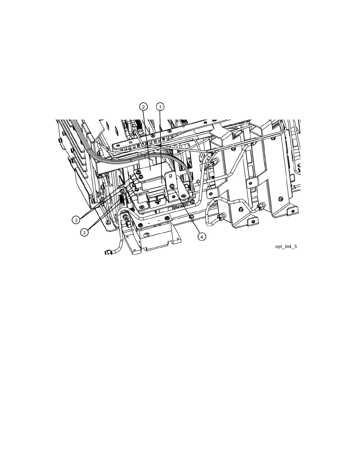
6. Refer to Figure 15-18. Using the T-10 driver, remove the single screw (4)
to separate the switch 2/bracket assembly (1)/(2) from the low band
switch bracket. To separate switch 2 (1) from it’s bracket (2), remove the
two 0515-1992 screws (3) using the T-8 driver.
Figure 15-18 Switch 2 Removal

 Loading...


