EasyManuals Logo

Keysight Technologies X Series Service Guide

Keysight Technologies X Series
671 pages
To Next Page IconTo Next Page
To Previous Page IconTo Previous Page
Page #491 background imageLoading...
Page #491 background image
Keysight N9010A EXA Service Guide 491
Assembly Replacement Procedures
RF Area (Option 503, 507, 513, 526)
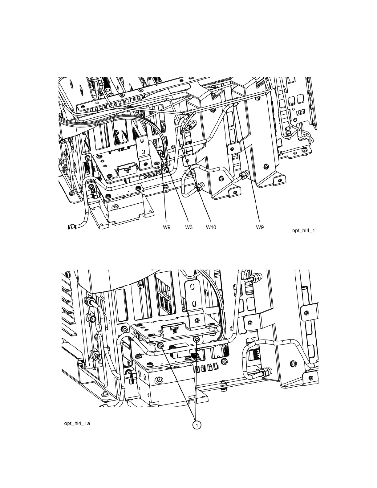
8. Refer to Figure 15-20. Remove the semi-rigid cables W3, W9, and W10.
Figure 15-20 Removing Coax Cables
9. Refer to Figure 15-21. Using the T-10 driver, remove the two screws (1) to
separate the low band switch/bracket from the chassis.
Figure 15-21 Low Band Switch/Bracket Removal

Table of Contents

Other manuals for Keysight Technologies X Series

Questions and Answers:

Question and Answer IconNeed help?

Do you have a question about the Keysight Technologies X Series and is the answer not in the manual?

Keysight Technologies X Series Specifications

General IconGeneral
BrandKeysight Technologies
ModelX Series
CategoryMeasuring Instruments
LanguageEnglish

Related product manuals