Keysight N9010A EXA Service Guide 589
Assembly Replacement Procedures
Front Frame Assembly
Display Assembly - LED
Removal
1. Refer to Figure 15-96. Remove the front panel shield by removing the four
screws (28).
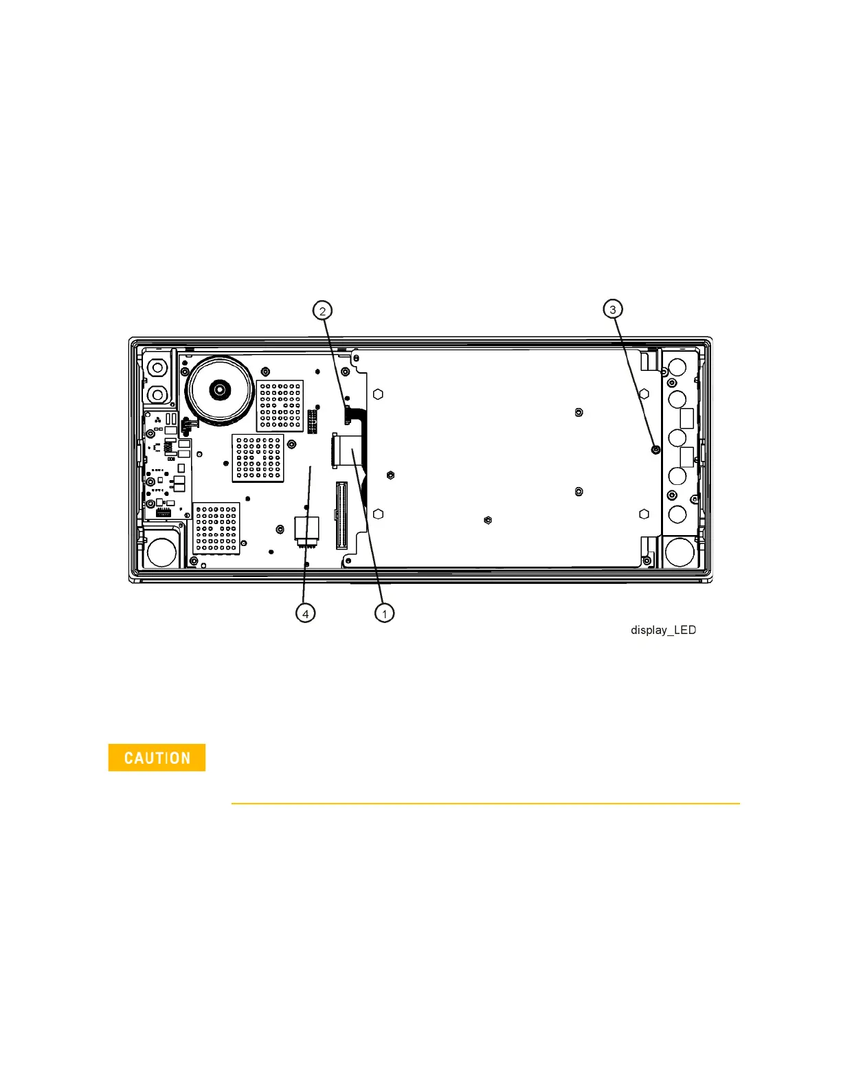
2. Refer to Figure 15-97. Disconnect the flex circuit A1W1 (1) and A1W3 (2)
from the front panel interface board (4).
Figure 15-97 Display Removal - LED
3. Remove the screw (3) securing the display bracket to the Front Frame
Assembly. The display can now be removed from the Front Frame
Assembly.
4. Refer to Figure 15-98. To separate the LCD (2) from the display bracket
(1), remove the four screws (3). When reassembling, torque the four
screws to 5 inch-pounds.
5. To separate the DC to DC Converter (4) from the display bracket (1),
remove the two screws (5). When reassembling, torque the two screws
to 9 inch-pounds.
Once the display assembly has been removed from the Front Frame Assembly, the glass filter is
no longer secured. DO NOT tip the assembly in such a manner that would cause it to fall out of
place, as this may cause injury and/or damage to the glass.

 Loading...


