240
2–A1. Installing the EXB-MOSS
Be sure that the AC power cable remains disconnected
until you have completed all steps of removing the
cover, installing the option board/memory, and re-
attaching the cover.
1 Make sure that cover “A” has been removed. (☞“1. Prep-
arations for installation,” “1–A. Removing cover “A” for
the EXB-SCSI or EXB-MOSS.”)
2 Remove the EXB-MOSS from its packing pouch.
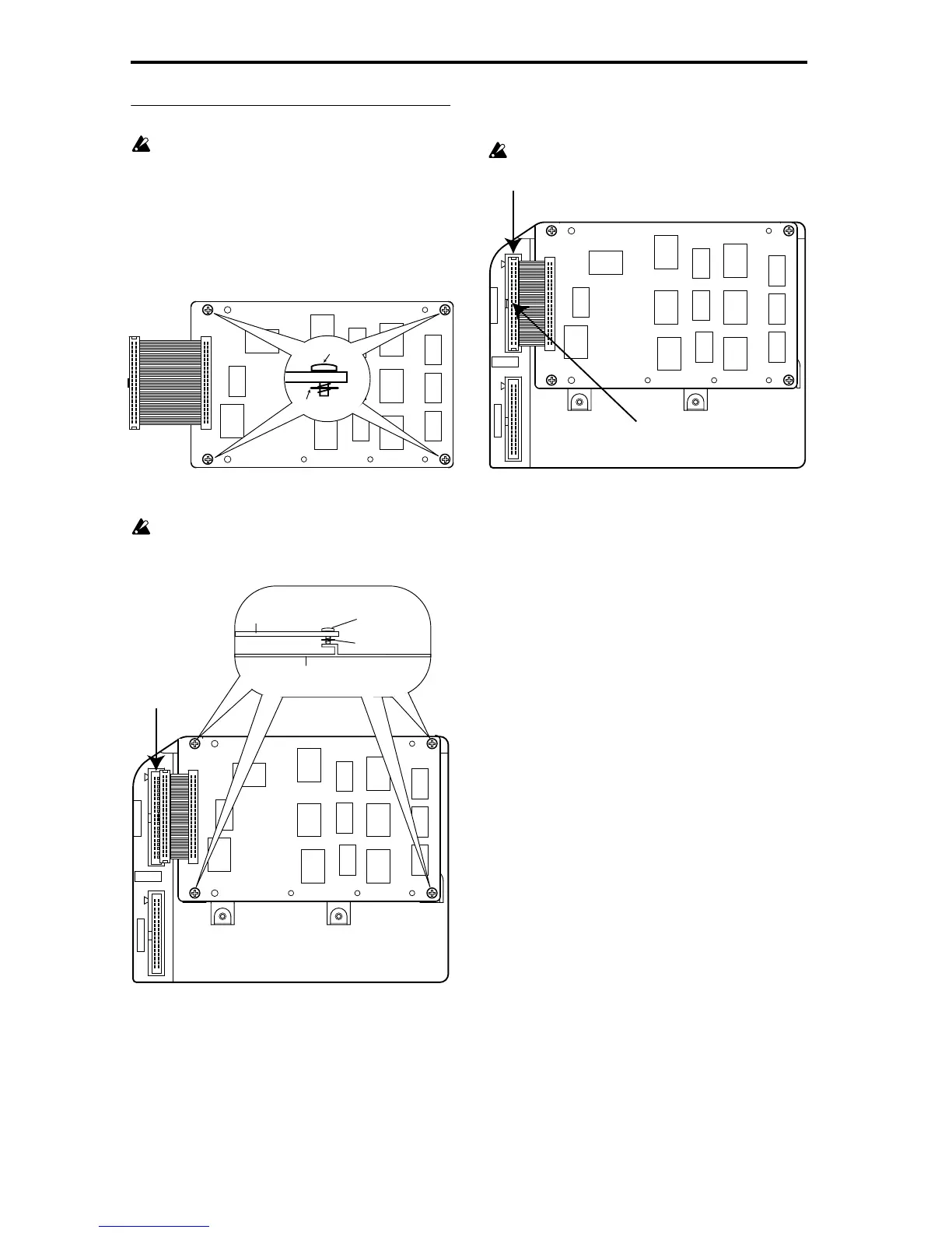
3 Note that screws and washers are attached to the four
corners of the board.
4 Use the four screws to attach the EXB-MOSS to the corre-
sponding brackets inside the TRITON.
Before the screws are tightened, the EXB-MOSS will
float slightly above the brackets. If at this time you
apply excessive force to the EXB-MOSS, the screws or
washers may come out.
5 Plug the cable into the connector as shown in the dia-
gram. Press the cable firmly in until it stops.
Do not touch any part of the circuit board other than
the connector in which the cable is being inserted.
6 Reversing the procedure by which you removed cover
“A,” re-attach the cover.
7 When all steps have been completed, turn on the power
and make sure that the EXB-MOSS has been installed
correctly. (
☞“Checking after installation”)
Screw
Washer
EXB–MOSS
EXB–SCSI
Screw
Washer
Chassis to which the board is
being installed
EXB-MOSS
Connector
EXB–MOSS
EXB–SCSI
Press in all the way
Connector
 Loading...