NET Series
Appendix B
LEIGHTRONIX, INC. Firmware Ver. 1.00.42/Software Ver. 1.0.2.6 Page 143
2010-07-09
SET SWITCHES
ASSIGN INTERFACE AN ADDRESS
Each PRO-BUS interface relays the LEIGHTRONIX Controller commands issued to its
address number. The interface’s activity LED toggles from its previous state (ON or
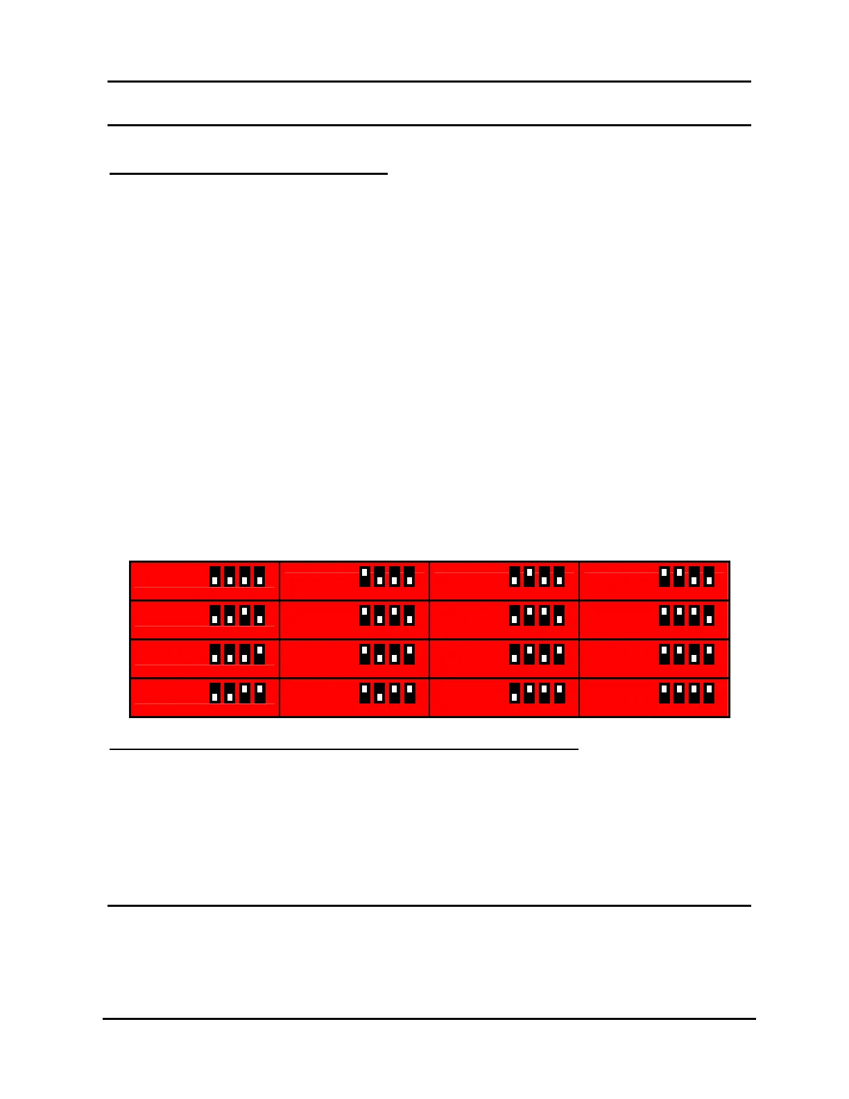
OFF) when the interface receives a command. To assign your interface an address,
set Switches 1–4 (see Illustration 109) according to Table 25, PRO-BUS Address
Configuration. For organizational purposes, please:
Assign your interfaces consecutive address numbers, starting with “01” at the
Controller.
If your Controller has two PRO-BUS ports, continue numbering the first
interface in the second PRO-BUS chain where the first chain left off.
NOTES:
For interfaces attached to a TCD/IP Controller, the address settings for
Switches 1–4 shown in Table 25, PRO-BUS Address Configuration are
repeated for each PRO-BUS chain (for example, Switches 1–4 for Device
1 and Device 17 are the same).
If possible, match each device’s interface address to its switcher input number.
Label devices and interfaces with their address and input numbers.
Document your entire PRO-BUS interface/device/switcher setup.
Table 25, PRO-BUS Address Configuration
DEVICE 01
DEVICE 02 DEVICE 03 DEVICE 04
DEVICE 05
DEVICE 06 DEVICE 07 DEVICE 08
DEVICE 09
DEVICE 10 DEVICE 11 DEVICE 12
DEVICE 13
DEVICE 14 DEVICE 15 DEVICE 16
CONFIGURE INTERFACE TO SEND CONTROL COMMANDS
When an interface receives a PRO-BUS command, it checks the settings of Switches
5–8 and emits the corresponding command(s). The emitted command(s) will change
the device from its initial, operational mode to a new mode. The settings for Switches
5–8 vary depending on the PRO-BUS interface model, so refer to the corresponding
PRO-BUS manual for more information.
ATTACH PRO-BUS TO CORRESPONDING DEVICE
LEIGHTRONIX PRO-BUS interfaces are sold separately for many brands and models
of professional video equipment and are available with infrared, mini-jack, and multi-
1 2 3 4