Manitowoc Published 08-12-19, Control # 224-13_v2 4-65
MLC650 OPERATOR MANUAL SET-UP AND INSTALLATION
Installing the First Crawler (continued)
See Figure 4-52 for the following procedure:
Figure shown without lifting jack cylinders for clarity.
NOTE: The crawler pins (4) are shipped in the retracted
position to meet shipping width requirements.
The collars (1a) are stored on the carbody and are
secured with retaining pins (2a) and hair-pin cotter
or safety pins (3a).
Reference Table 4-3
for swing limits during crane assembly
and disassembly.
14. Slowly lower the crawler, mast up, and swing to engage
the crawler hooks (5) with the carbody pins (6).
15. Stop lowering when the crawler hooks are fully engaged
and the carbody pins and the connecting holes are
aligned.
16. Using the remote control, deploy the crawler pin (4).
17. Secure the crawler pin with collar (1b), the retaining pin
(2b), and the cotter pin (3b) on the front and rear of the
crawler.
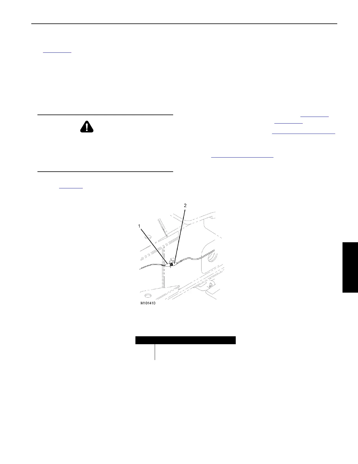
18. Connect the carbody electrical cable (1, Figure 4-53
) to
the crawler electrical cable (2, Figure 4-53
).
19. Remove the slings (2 and 3, Figure 4-50 on page 4-62
)
from the lifting brackets on the crawler frame.
20. Remove the pins from the crawler lifting brackets
(6a, Figure 4-50 on page 4-62
), place the lifting brackets
into the stored position, and secure them with pins and
safety pins.
WARNING
Crane Tipping Hazard!
To avoid serious or fatal crushing injury, do not
exceed operating radii and capacities given in the
Liftcrane Mast Handling Capacities Chart. Structural
failure or crane tipping will occur.
FIGURE 4-53
Item Description
1 Carbody Electrical Cable (WLC2)
2 Crawler Electrical Cable (WLL1-P1)
Shown Without Lifting Jack Cylinders for Clarity