Manitowoc Published 08-12-19, Control # 224-13_v2 4-97
MLC650 OPERATOR MANUAL SET-UP AND INSTALLATION
See Figure 4-74, for the following steps:
7. Lift the next insert into position and engage the fixed
horizontal pins (1, View A) with the hooked connectors
(2) on the adjacent insert.
8. Lower the insert (7) until the bottom connector holes are
aligned.
9. If equipped with hydraulically connected bottom pins:
a. Remove the safety pins (3, View B) from the
shipping position in pins (5a).
b. Install the pins using the hand-held pin puller (4,
View C). See "Connect Hand-Held Pin Puller" on
page 4-37.
c. Install the safety pins (3, View C). and remove the
hand-held pin puller (4).
10. If equipped with manually connected bottom pins:
a. Remove the pins (8, View D) from the storage
brackets (9) on the adjacent section.
b. Install the pins (8, View E) in the connecting holes
between the sections.
11. Block under the top end of the insert. The blocking can
be moved from the end of one insert to the end of the
next insert.
If noted in the Boom Rigging Drawing, block under
the boom sections at the specified locations to
prevent damage caused by excessive sag in long
boom combinations.
12. Disconnect the lifting slings.
13. If necessary per the Boom Rigging Drawing being used,
perform the following steps as the boom inserts are
assembled:
- "Deploy Luffing Jib Wire Rope Guide" on page 4-97
- "Install Intermediate Wire Rope Guide" on page 4-
99
- "Install Drop-Down Suspension" on page 4-101
- Install Intermediate Suspension Insert at proper
location (see "Prepare Intermediate Suspension
Pendants" on page 4-135)
14. Repeat the above steps until all inserts are installed in
the PROPER SEQUENCE.
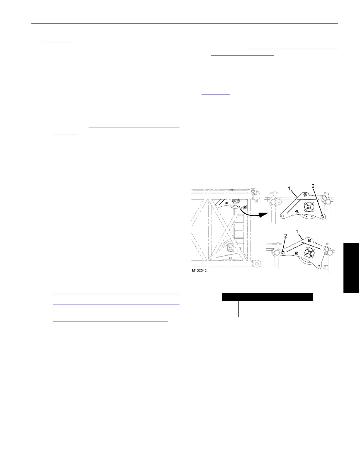
Deploy Luffing Jib Wire Rope Guide
See Figure 4-75 for the following.
If the crane will be rigged with a luffing jib, raise the luffing
hoist wire rope guide as follows:
1. Attach a lifting sling to the wire rope guide (1).
2. Remove the safety pin and pin (2).
3. Raise the rope guide the working position and install the
pin (2) and safety pin.
4. Disconnect the lifting sling.
FIGURE 4-75
Item Description
1 Wire Rope Guide
2 Pin and Safety Pin
WORKING POSITION
STORED POSITION