Manitowoc Published 08-12-19, Control # 224-13_v2 4-139
MLC650 OPERATOR MANUAL SET-UP AND INSTALLATION
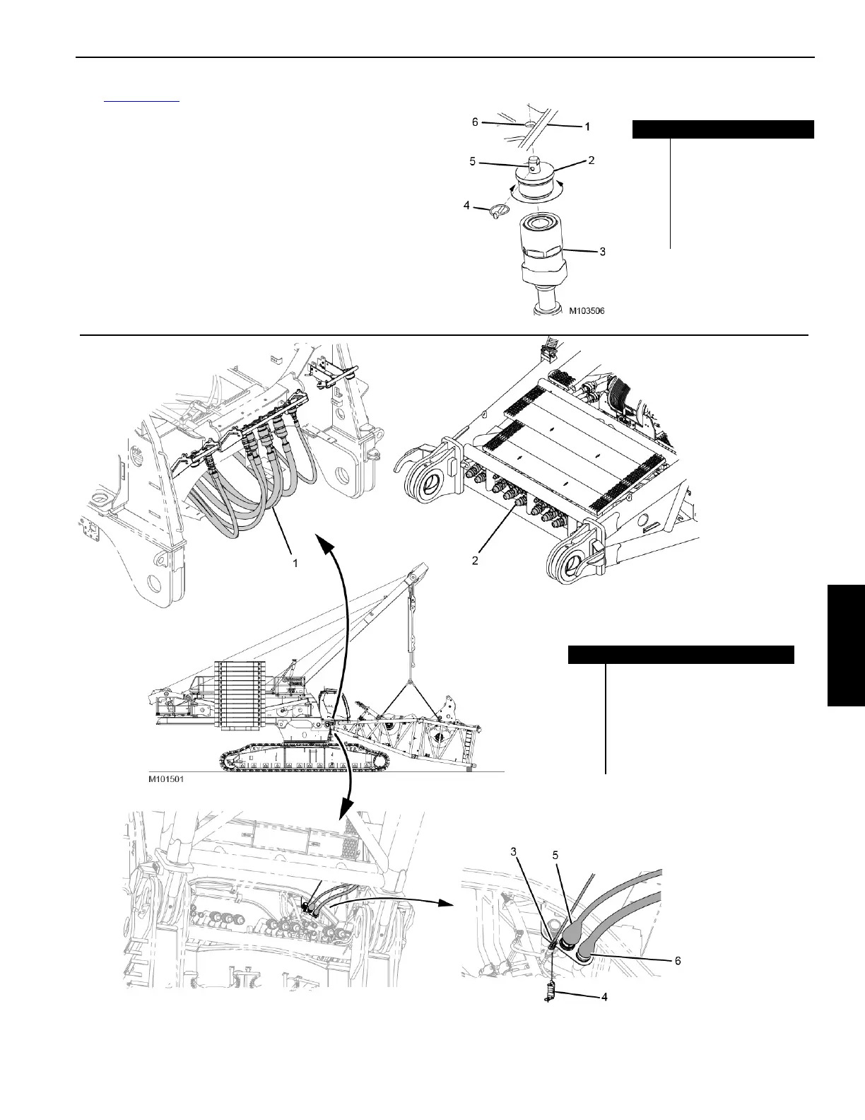
See Figure 4-105 for the following procedure:
1. Hold onto the mounting plug (2) and remove the locking
pin (4).
2. Disconnect the hose coupler (3) from its working
position and screw the mounting plug into the hose
coupler.
3. Align the mounting plug pin (5) with the mounting
bracket hole (6) on the mounting bracket (1) and secure
with the locking pin.
4. Repeat steps for remaining hoses.
FIGURE 4-105
Item Description
1 Mounting Bracket
2 Mounting Plug
3 Hose Coupler
4 Locking Pin
5 Mounting Plug Pin
6 Mounting Bracket Hole
FIGURE 4-106
Item Description
1Hydraulic Hose (stored) (qty 8)
2 Hydraulic Connector (boom butt)
3 Electric Cable—CAN D
4 CAN Terminator
5 WBB2 Cable Connect to WFR2
6 WBB1 Cable Connect to WRL2