3B-390-13645--2 1095 OIL INJECTION SYSTEM
Bleeding Air from Oil
Injection System
IMPORTANT: If air exists in either oil pump hose
(inlet or outlet), the air MUST BE bled from the
hose(s) before operating engine.
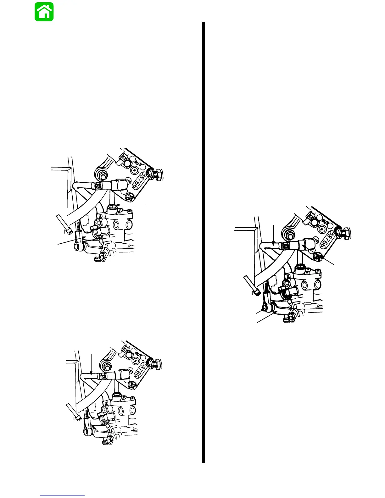
Bleeding Air from Oil Pump Inlet Hose
1. With engine not running, place a shop towel be-
low the oil pump. Loosen bleed screw three to four
turns and allow oil to flow from bleed hole until no
air bubbles are present in inlet hose. Torque bleed
screw to 25 lb. in. (2.8 Nm). This procedure also
allows oil pump to fill with oil.
22988
a
b
a - Bleed Screw
b - Inlet Hose
Bleeding Air from
Oil Pump Outlet Hose
1. Purge air from outlet hose, by running engine at
idle speed, until no air bubbles are present in out-
let hose.
22988
a
a - Outlet Hose
Oil Pump Test
NOTE:
A graduated container is required to perform
this test.
1. Connect engine to remote fuel tank containing a
50:1 fuel/oil mixture (25:1 if during break-in
period).
2. Attach flush device to outboard or place outboard
in test tank.
3. Remove top cowling.
4. Disconnect oil outlet hose from fuel pump fitting.
5. Plug fuel pump fitting.
6. Remove link rod end from oil flow regulator.
7. Rotate oil pump regulator full counterclockwise
and hold it in this position, (wide-open pump posi-
tion).
8. Attach an accurate service tachometer to engine.
9. Place end of hose into graduated container.
22988
b
c
d
a
a - Outlet Hose
b - Fuel Pump Fitting
c - Link Rod End
d - Pump Regulator
10. Run engine at 700 RPM for 15 minutes.
11. 3 Cylinder:
pump # 42959/42959--1/42959--2 = 21 ± 1.9cc
pump # 42959--3 = 25 ± 2.3cc
4 Cylinder:
pump # 44345/44345--1/44345--2 = 28.6 ± 2.6cc
pump # 44345--3 = 33.3 ± 4cc
NOTE:
Pump output specifications are derived at 70
degrees room temperature. Cooler or warmer test
temperature will result in LESS oil pump discharge.