7A-3ENGINE ATTACHMENTS90-13645--2 495
Parallel Routed Steering
Cables and Attaching Kit
Installation
(Both Steering Cables Routed Together Down
Starboard Side of Boat)
Super Ride-Guide Steering Kit
Installation
IMPORTANT: It may be necessary to install steer-
ing cable into tilt tube of starboard engine before
mounting engine.
Both gear racks or rotary steering heads must be
installed so that both steering cables will be
routed together on the same side of the boat and
will push-and-pull together.
1. Install Super Ride-Guide Steering Kit in accor-
dance with instructions included with Super Ride-
Guide Kit.
2. Make sure that both gear racks or rotary steering
heads are installed so that both steering cables
are routed together and will push-and-pull togeth-
er (Figure 1).
a
b
a
b
a - Straight Rack (Left); Rotary Steering (Right)
b - Steering Cables (Install so that Both Cables Will
Push-and-pull Together.)
Figure 1. Super Ride-Guide Steering Kits Installed
WARNING
Before using engine after installation of cables,
check to see that boat will turn right when steering
wheel is turned right and that boat will turn left
when wheel is turned left. Do this check at all tilt
angles and thru full range of turn angles.
Installing Steering Cables and
Steering Link Rods to Engines
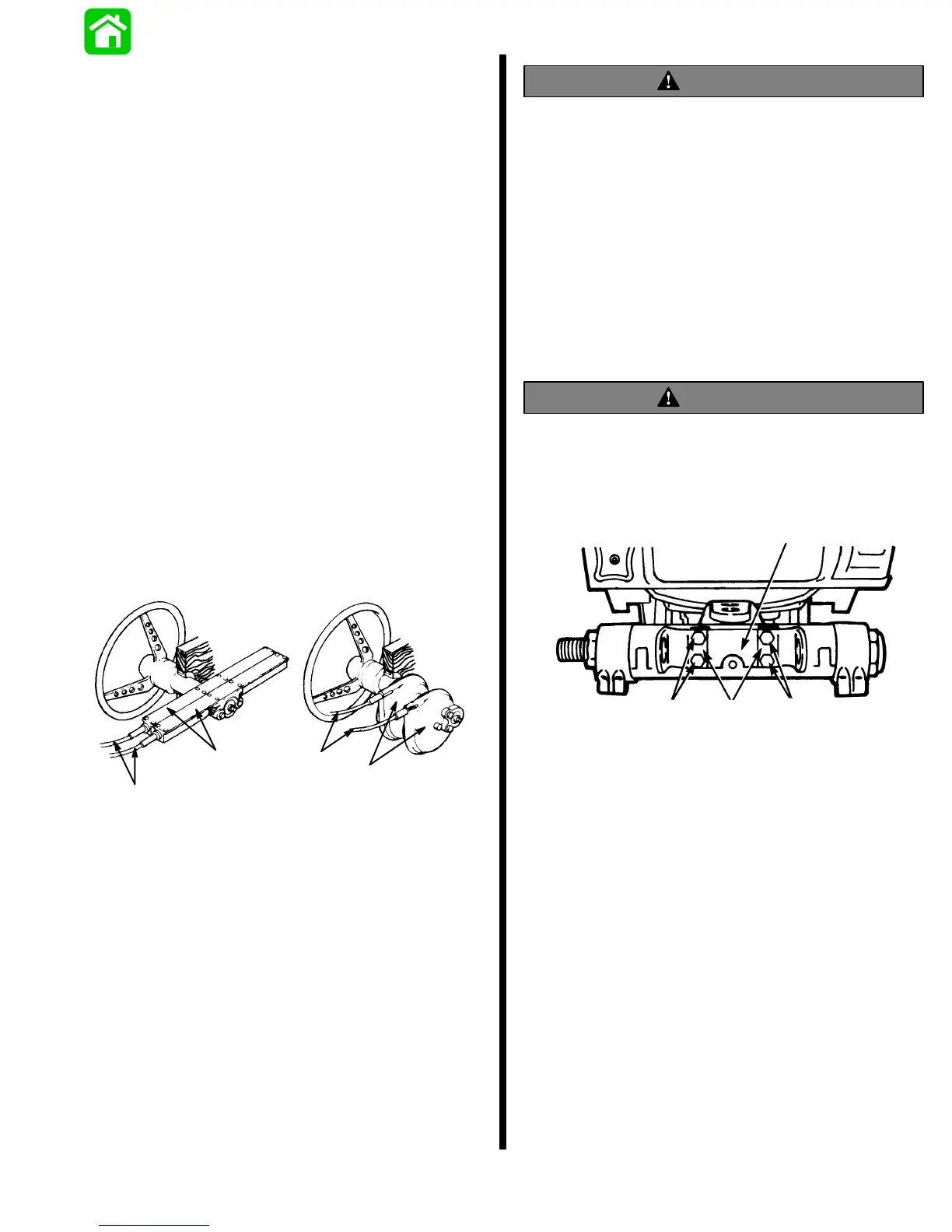
1. Install tube mounting bracket (Figure 2) to star-
board mounted engine with 2 locking retainers
and 4 bolts. Torque bolts to 100 lbs. in. (11.3 Nm)
and bend end of locking retainers up and against
flat on each bolt, as shown in Figure 2.
WARNING
Locking retainer ends must be bent up and
against flat on each bolt, that secures mounting
bracket to engine, to prevent bolts from turning
out.
16958
a
b
c
b
a - Tube Mounting Bracket
b - Bolts
c - Locking Retainers (Bend Ends Up and Against
Flat on Bolts.)
Figure 2. Tube Mounting Bracket Installed