2B-1590-13645--2 495 ELECTRICAL AND IGNITION
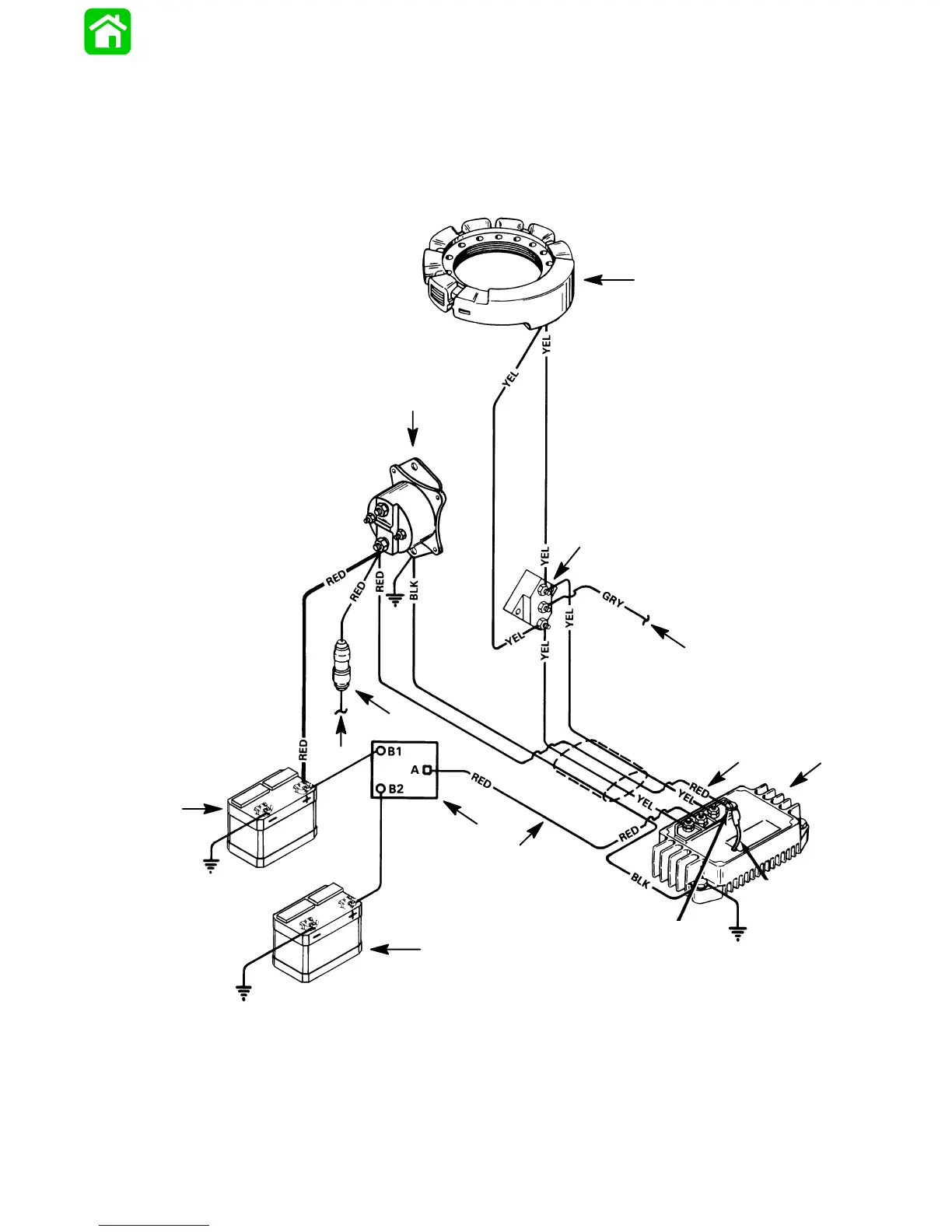
4 Cylinder Battery Charging Diagram
with Battery Isolator
IMPORTANT: After electrical connections are
made, coat all terminal connections using Quick-
silver Liquid Neoprene (92-25711), to avoid corro-
sion.
50404
Screw Size
#10-16x3/8”
P/N 10-62568
User Supplied Red Lead
(10 Gauge Minimum Diameter
with Protective Abrasive Sleeve
Installed)
Move Lead From Red
Stud to Position Shown
BLK BLACK
BLU BLUE
GRY GRAY
RED RED
YEL YELLOW
Move Red Lead From
Start Solenoid to
Position Shown
a
b
c
d
e
f
g
h
i
j
a - Stator
b - Terminal Block
c - To Tachometer
d - Voltage Regulator/Rectifier
e - Battery Isolator
f - Auxiliary Battery
g - Start Battery
h - To Remote Control Harness
i - 20 Ampere Fuse
j - Starter Solenoid