2B-590-13645--2 495 ELECTRICAL AND IGNITION
Battery Charging System
Troubleshooting
A fault in the battery charging system usually will
cause the battery to become undercharged. Check
battery electrolyte level, and charge battery. See
“Electrolyte Level”, and “Charging a Discharged
Battery”.
If battery will NOT accept a satisfactory charge, re-
place battery.
If battery accepts a satisfactory charge, determine
the cause of the charging system problem as follows.
1. Check for correct battery polarity [RED cable to
positive (+) battery terminal]. If polarity was incor-
rect, check for damaged rectifier. See “Rectifier
Test”, following.
2. Check for loose or corroded battery connections.
3. Visually inspect wiring between stator and battery
for cuts, chafing; and disconnected, loose or cor-
roded connection.
4. Excessive electrical load (from too many acces-
sories) will cause battery to run down.
If visual inspection determines that battery connec-
tions and wiring are OK, perform the following stator
and rectifier tests.
Stator Ohms Test
(Alternator Coils Only)
NOTE:
Stator can be tested without removing from
engine.
1. Disconnect both YELLOW (stator leads) from ter-
minals on rectifier (or terminal block).
2. Use an ohmmeter and perform the following test.
IMPORTANT: If stator is mounted on engine, black
stator lead (if provided) must be grounded to pow-
erhead when testing.
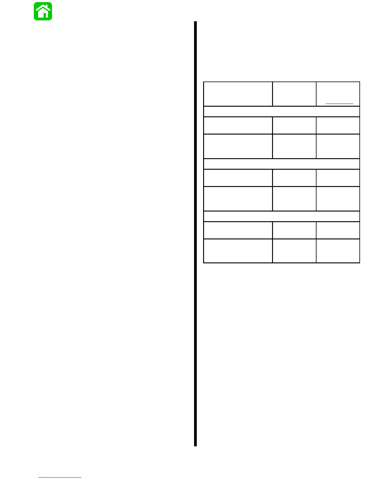
3. Replace stator if readings are outside ranges
shown.
Test Leads
Resistance
(Ohms)
Scale
Reading
(x
)
9 AMPERE STATOR
Between YELLOW
stator leads
.6 – 1.1*
.6 – 1.1*
(R x 1)
Between either
YELLOW stator lead
and engine ground**
No
Continuity
No
Continuity
(R x 1000)
16 AMPERE STATOR
Between YELLOW
stator leads
.17 – .19
.17 – .19
(R x 1)
Between either
YELLOW stator lead
and engine ground**
No
Continuity
No
Continuity
(R x 1000)
24 AMPERE STATOR
Between YELLOW
stator leads
.05 – .15
.05 – .15
(R x 1)
Between either
YELLOW stator lead
and engine ground**
No
Continuity
No
Continuity
(R x 1000)
* DC resistance of these windings generally is less
than 1.5 ohms. If a reading (resembling a short) is
obtained, this would be acceptable.
** If stator is removed from engine, connect test lead
to black stator lead, if provided.
4. If meter readings are other than specified, replace
stator.