6A-35POWER TRIM90-13645--2 495
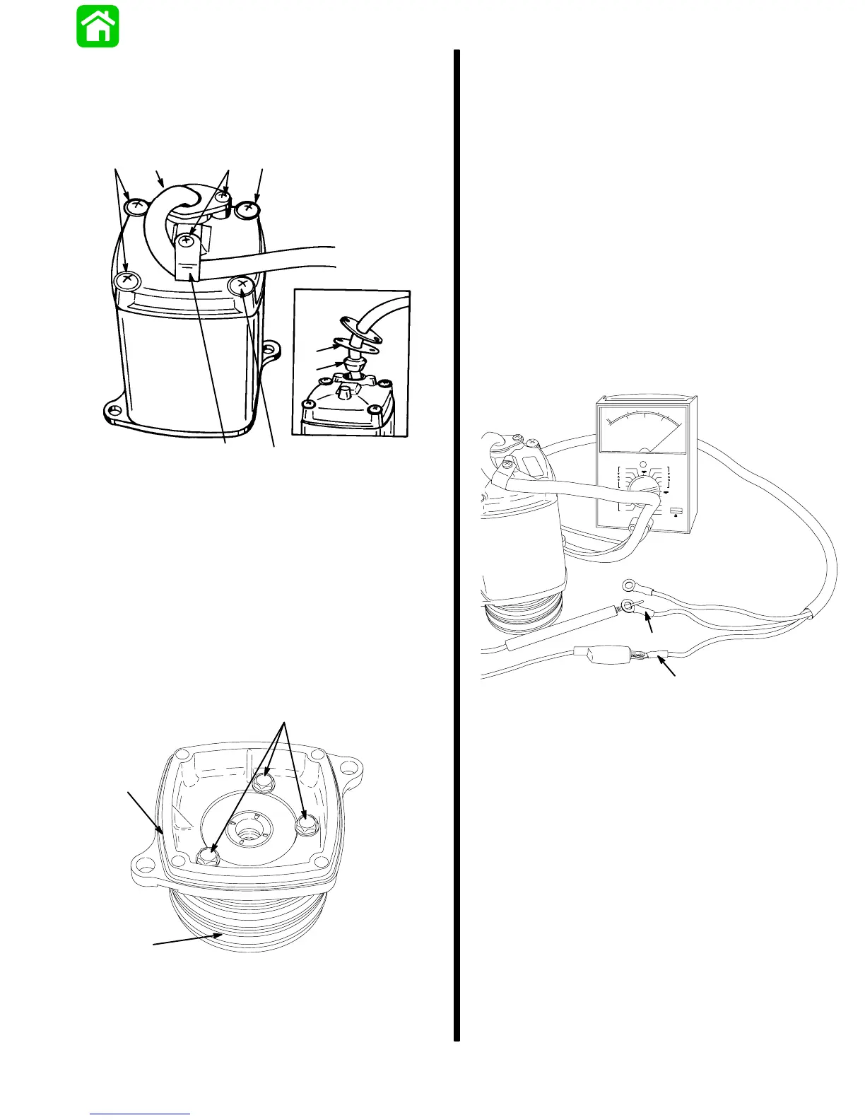
2. Remove screws and clamp.
Remove screws.
Lift motor from end cap, taking care not to drop
armature.
51345
a
b
c
d
e
a
c
c
a - Screw (3)
b - Clamp
c - Screw (4)
d - Gasket
e - Grommet
3. Remove bolts.
NOTE:
Some motors use 2 bolts to secure end frame
cap.
Lift end cap from pump.
Follow “Reassembly” and “Installation” instruc-
tions in “Motor Repair,” following.
18469
a
b
c
a - Bolts
b - End Cap
c - Pump
Motor and Electrical
Tests/Repair
Thermal Overload Switch Test
IMPORTANT: If trim pump has just been operated,
do not run pump for approximately one minute be-
fore testing thermal overload switch. After this
period of time the switch should close (reset it-
self) and pump again may be operated. Perform
the following check(s) only if switch does not re-
set itself.
MOTOR ASSEMBLED
Connect Ohmmeter (R x 1 scale) leads as shown. If
switch is good, full continuity (zero ohms) will be indi-
cated. If full continuity is not indicated, disassemble
motor and recheck switch per instructions, following.
18459
a
b
a - Motor Wire (BLUE)
b - Motor Wire (BLACK)