7A-6 ENGINE ATTACHMENTS 90-13645--2 495
abcde ae
50061
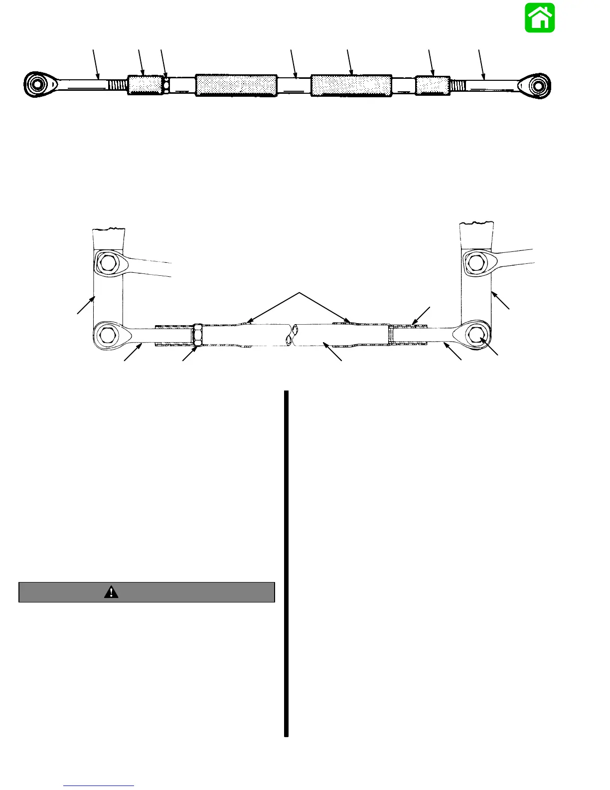
a - Rubber Bushing
b - Rubber Sleeve
c - Jam Nut; Torque to 20 lbs. ft. (27.1 Nm)
d - Coupler
e - Steering Eye
Figure 9. Coupler Assembled
a
b
cd
e
f
g
d
b
a - Jam Nut; Torque to 20 lbs. ft. (27.1 Nm)
b - Engine Steering Arm
c - Coupler
d - Steering Eye
e - Rubber Sleeves
f - Rubber Bushings
g - Pivot Bolt and Locknut
Figure 10. Coupler Parts Sequence
8. Secure coupler with jam nut, as shown in Figures
9 and 10, and torque to 20 lbs. ft. (27.1 Nm).
9. Position rubber bushings as shown above.
10. Slide both rubber sleeves over exposed threads
on each steering eye (Figure 10).
WARNING
Tension adjustment – steering cable mounting
tube must be adjusted away from end of steering
cable when adding tension to steering system (to
remove slack). Failure to adjust tube this way may
result in hard steering, if one engine is tilted up
while operating boat.
Steering System Tension Adjustment
(Parallel Routed Steering Cables)
IMPORTANT: After this Ride-Guide Attachment
Kit is installed, there must be proper tension in the
steering system. Not enough tension will cause
slack (play) in steering system. Too much tension
will cause steering cables to bind. Perform Step
1, following, to adjust for correct tension.
1. Loosen adjustment nuts and push steering cable
mounting tube (by-hand) toward end of steering
cable (to remove slack in steering system). Tight-
en adjustment nuts and check system for slack
(play) or too much tightness. If steering system is
too tight, readjust tube away from end of steering
cable (Figure 11) or, if too much slack (play) exists
in system, readjust tube toward end of steering
cable (Figure 11). Tighten nuts and readjust, if
necessary.