4A-20 90-13645--2 495POWERHEAD
a
b
c
d
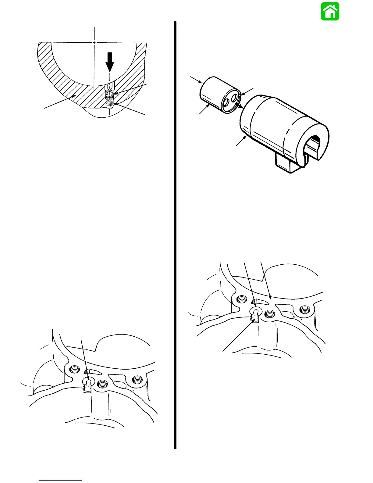
a - Crankcase Cover
b - Check Valve Assembly P/N 21-42657A1
c - Valve Restrictor P/N 22-814204
d - Install From Crankshaft Side
Check Valve/Restrictor Assembly
7. Verify check balls are free to move in check valve
case after installation. If check balls are not loose,
check valve case was damaged during installa-
tion and MUST BE replaced.
8. Reassemble powerhead per appropriate service
manual instructions and reinstall on driveshaft
housing.
DESIGN 3 (MODELS WITH CHECK VALVE AND
CARRIER)
NOTE:
DESIGN 3 check valves may be replaced
without splitting crankcase halves.
REMOVAL
1. Remove carburetors and intake manifold/reed
block assemblies. Refer to page 4A-10/11 for
procedure.
2. Grasp carrier and remove carrier/check valve as-
sembly from crankcase cover.
51621
a
a - Carrier/Check Valve Assembly
3. Push check valve out of carrier. If nylon ball within
check valve is stuck or carrier is charred, replace
check valve and/or carrier as required.
IMPORTANT: SINGLE HOLE side of check valve
MUST FACE CRANKCASE.
51131
a
b
c
d
a - Check Valve
b - Carrier
c - Single Hole
d - Double Hole
INSTALLATION
1. Install check valve (if removed) inside of carrier
(single hole of valve faces tapered end of carrier).
2. Align carrier tab with slot in crankcase cover and
insert check valve/carrier assembly into cover.
51621
a
b
c
a - Check Valve/Carrier Assembly
b - Slot
c - Crankcase Cover