90-13645--2 10953B-4 OIL INJECTION SYSTEM
Low Oil Sensor Test
NOTE:
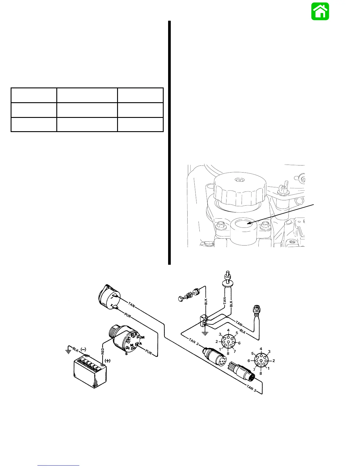
Low oil sensor is located in bottom of oil tank.
1. Disconnect low oil sensor leads (tan and black)
from terminal block.
2. Using an ohmmeter, perform both tests in chart,
following.
Oil Level in
Oil Tank
Test Leads
Between
Scale Reading
(x__________)
1/2 Full to Full
Low Oil Sensor Leads
(tan and black)
No Continuity*
(R x 1)
Empty
Low Oil Sensor Leads
(tan and black)
Continuity**
(R x 1)
* If continuity is indicated, check to see if float (located inside oil
tank) is stuck in place or if magnet (attached to bottom of float)
has come loose. If float checks O.K., replace sensor.
** If continuity is NOT indicated, check to see if float (located
inside oil tank) is stuck in place. If float is NOT stuck in place,
replace sensor (bottom of oil tank – remove screw and retract
sensor).
Warning Horn System
Models Equipped with Test Button
(3 Cylinder Only)
DESCRIPTION
Major components of the warning horn system are an
ignition switch, warning horn, low oil sensor,
powerhead temperature sensor, and warning horn
test button.
With the ignition switch in the “Run” position, electrical
current is routed thru the warning horn and supplied
to the powerhead temperature sensor, low oil sensor,
and warning horn test button. If the powerhead
overheats, the oil level in the oil tank drops below
approximately 1 quart (.95 liter), or the warning horn
test button is depressed, the electrical circuit
completed, and the warning horn will sound.
WARNING HORN SYSTEM CHECK
IMPORTANT: Warning horn will sound if power-
head is overheated or if oil level in oil tank has
dropped below approximately 1 quart (.95 liter).
1. Turn ignition key switch to “Run” position.
2. Depress test button. Warning horn will sound if
system is functioning properly.
3. Turn key switch to “Off” position.
25955
a
a - Test Button
 Loading...