6C-18 90-13645--2 495POWER-TRIM
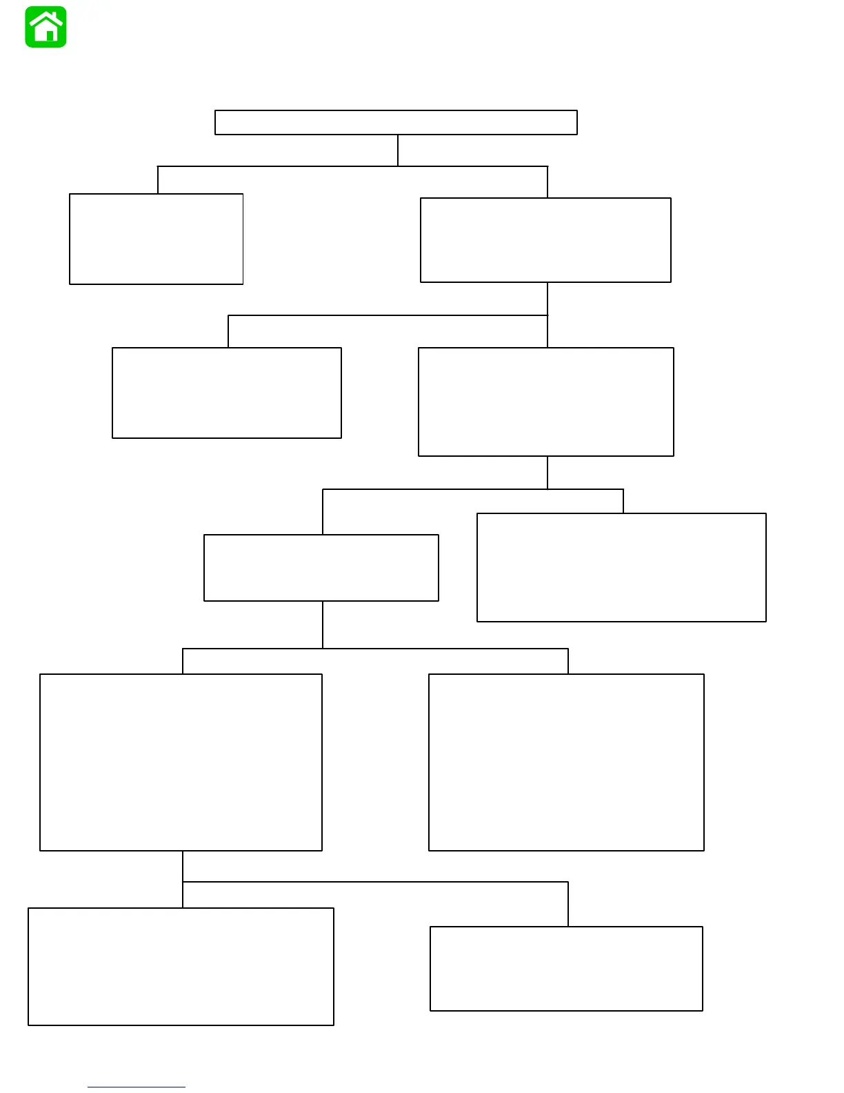
Troubleshooting the “Down” and “Up” Circuits (All Circuits Inoperative)*
*Remote Control NOT Equipped with Trailer Button
Battery Voltage Indicated:
S Connect Voltmeter red lead to
Point 8 and black lead to ground.
S Depress “Up” trim button and
check for battery voltage.
No Voltage Indicated:
Red wire is open between Point 3 and red
terminal on back of the ignition switch.
S Check for loose or corroded connections.
S Check for open circuit in wire.
Battery Voltage Indicated:
S Check black ground wires for poor
connection or poor ground.
S Pump motor is faulty. Refer to “Motor
and Electrical Tests/Repair,” following.
Battery Voltage Indicated:
Trim switch is faulty or there is an open
circuit in wires (green-white, blue-white)
between trim buttons and trim pump.
S Check trim switch.
S Check all trim harness connectors
for loose or corroded connections.
S Check for pinched or severed wires.
Battery Voltage Indicated:
There is an open circuit in wire between
Point 5 and Red terminal on the back of
the ignition switch.
No Voltage Indicated:
Check that voltage is being supplied to
control by performing the following
checks:
S DO NOT start engine.
S Turn ignition switch to “Run” position.
S Check for voltage at any instrument,
using a Voltmeter.
No Voltage Indicated:
Connect red Voltmeter lead to
Point 5, and black lead to ground.
No Voltage Indicated:
S Check battery leads for poor
connections or open circuits.
S Check battery charge.
Blown Fuse:
S Correct problem that
caused fuse to blow.
S Replace fuse.
Fuse Not Blown:
Connect Voltmeter red lead to Point
3 and black lead to ground, Battery
voltage should be indicated.
Check in-line fuse (under cowl) to see if fuse is blown