7A-12 ENGINE ATTACHMENTS 90-13645--2 495
dc
b
a
51887
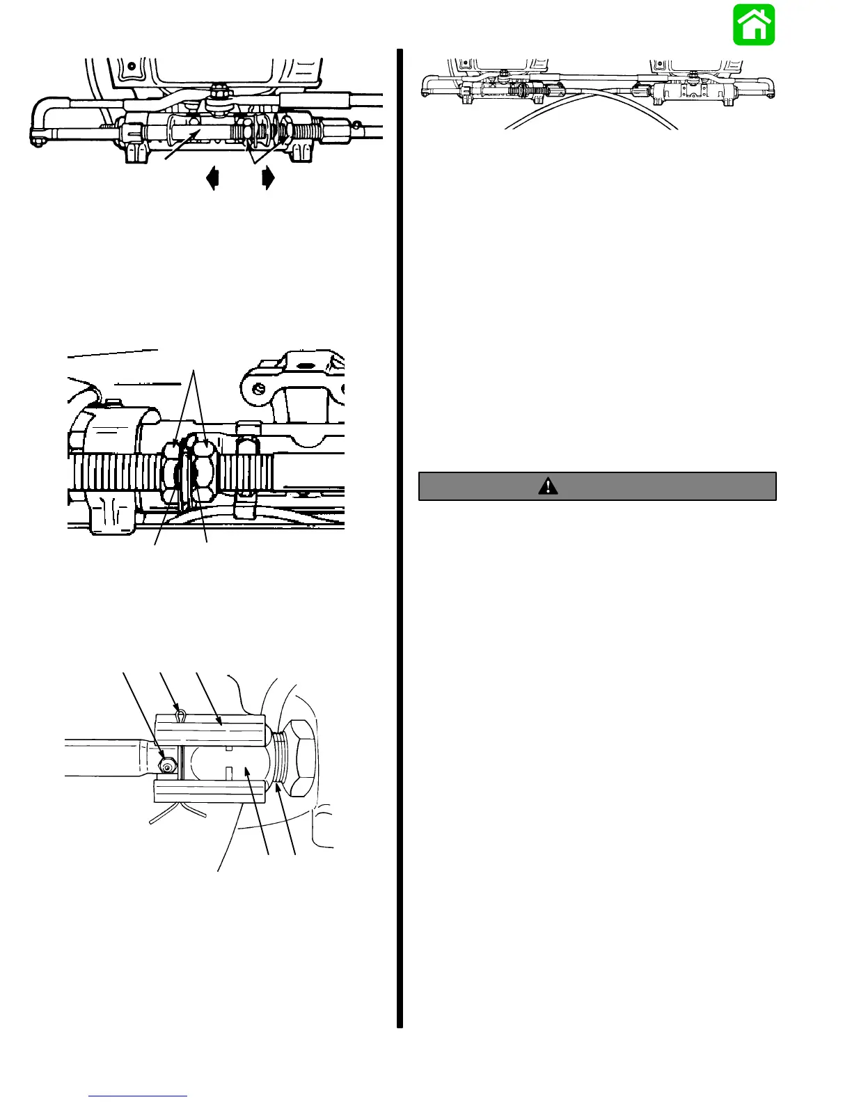
a - Steering Cable Mounting Tube
b - Adjustment Nuts
c - Adjust Tube in This Direction to Remove Slack from Steering
System
d - Adjust Tube in This Direction to Reduce Tightness from
Steering System
Figure 10. Steering System Tension Adjustment
(Opposite Side Routed Steering Cables)
51887
a
b
b
a - Adjust Nuts; Torque to 35 lbs. ft. (47.5 Nm)
b - Tab Lockwashers (Bend Against Flat on Each Nut.)
Figure 11. Adjustment Nuts Secured with Lock-
tabs
d
a
bc
e
51888
a - Steering Cable Attaching Nut;Torque to 35 lbs. in. (47.5 Nm)
b - Locking Sleeve (Provided with Ride-Guide Steering Cables)
c - Cotter Pin
d - Grease Fitting
e - Cable Guide Tube
Figure 12. Steering Cables Fastened to Tubes
50101
Figure 13. Attachment Kit Installation Complete
2. After steering system tension is adjusted correct-
ly, torque adjustment nuts (Figure 11) to 35 lbs. ft.
(47.5 Nm) and bend a tab lockwasher against a
flat on each nut.
3. Secure each steering cable attaching nut to tubes
by torquing steering cable attaching nuts
(Figure 12) to 35 lbs. ft. (47.5 Nm).
4. Install rubber bumpers on inside of locking
sleeves, then install a locking sleeve over each
steering cable attaching nut and secure with cot-
ter pin. Spread ends of cotter pin. Be sure to install
cotter pin so that it is located in-between attaching
nut and grease fitting (Figure 12).
5. Install new trim tabs as outlined in “Trim Tab Instal-
lation,” following.
WARNING
After installation is complete (and before
operating engine), check that boat will turn right
when steering wheel is turned right and that boat
will turn left when steering wheel is turned left.
Check steering thru full range (left and right) at all
tilt angles to assure interference-free movement.
Trim Tab Installation
IMPORTANT: With dual engine installation, exist-
ing trim tabs MUST BE replaced with new trim
tabs (supplied with kit).
1. Install new trim tabs as follows:
a. Shift engine controls into neutral and turn igni-
tion keys to “Off” position.
b. Remove plastic cap from rear of both drive shaft
housings, loosen bolt, that secures trim tab to
gear housing, and remove both trim tabs from
gear housing.
c. Install special trim tabs (supplied with kit) to
both gear housings, using existing bolts. Tight-
en bolts securely. Initial trim tab setting should
be straight to rear of engine. Replace plastic
caps on drive shaft housing.