4A-34 90-13645--2 395POWERHEAD
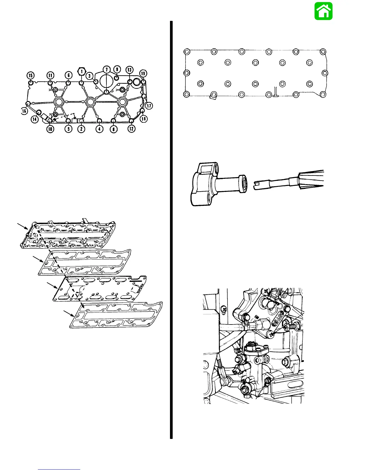
NOTE:
Keep clips positioned, as shown, during
torque sequence.
CYLINDER HEAD COVER TORQUE SEQUENCE
All Cover Bolts: 18 lb. ft. (24.4 Nm)
Exhaust Plate Cover and Exhaust
Divider Plate
Assemble in order shown.
a. Exhaust Plate Gasket
b. Divider Plate
c. Exhaust Plate Gasket
d. Exhaust Plate Cover
a
b
c
d
Insert bolts (24) and finger tighten.
Torque bolts in sequence.
EXHAUST PLATE COVER TORQUE SEQUENCE
All Cover Bolts: 18 lb. ft. (24.4 Nm)
22
17
23
18
24 14
10
13
9
6
5
1
2
4
8
7
311
15
16
19
21
20
12
Reinstall Oil Injection Pump Shaft and housing;
check O-rings - replace as necessary.
IMPORTANT: Insure that gears engage properly
and that the O-rings are seated properly on reas-
sembly, or an oil injection failure could occur, re-
sulting in possible powerhead damage.
20041
IMPORTANT: After reinstalling shaft and housing,
turn crankshaft - make sure oil pump shaft turns.
Reinstall Oil Injection Pump - 2 bolts. Torque to 60
lb. in. (6.8 Nm).
Reinstall Fuel Pump - 2 screws. Torque to
55 lb. in. (6.2 Nm).
Reattach fuel/oil line hoses and secure with stay-
straps.
19056
a
b
a - Screws [Torque to 55 lb. in. (6.2 N·m)]
b - Bolts [Torque to 60 lb. in. (6.8 N·m)]