2B-2390-13645--2 495 ELECTRICAL AND IGNITION
CHECKING POSITIVE BRUSHES AND
TERMINAL
Set ohmmeter to (R x 1 scale). Connect meter leads
between POSITIVE brushes. Meter must indicate full
continuity or zero resistance. If resistance is indi-
cated, inspect lead to brush and lead to POSITIVE
terminal solder connection. If connection cannot be
repaired, brushes must be replaced.
11673
a
a
a - POSITIVE (+) Brushes
TESTING NEGATIVE BRUSHES FOR GROUND
Set ohmmeter to (R x 1 scale). Place one lead of the
ohmmeter on the NEGATIVE brush and the other
lead on the end cap (bare metal). If the meter indi-
cates NO continuity, replace the NEGATIVE brush.
Repeat this procedure on the other NEGATIVE
brush.
11674
a
b
a - NEGATIVE (–) Brushes
b - End Cap
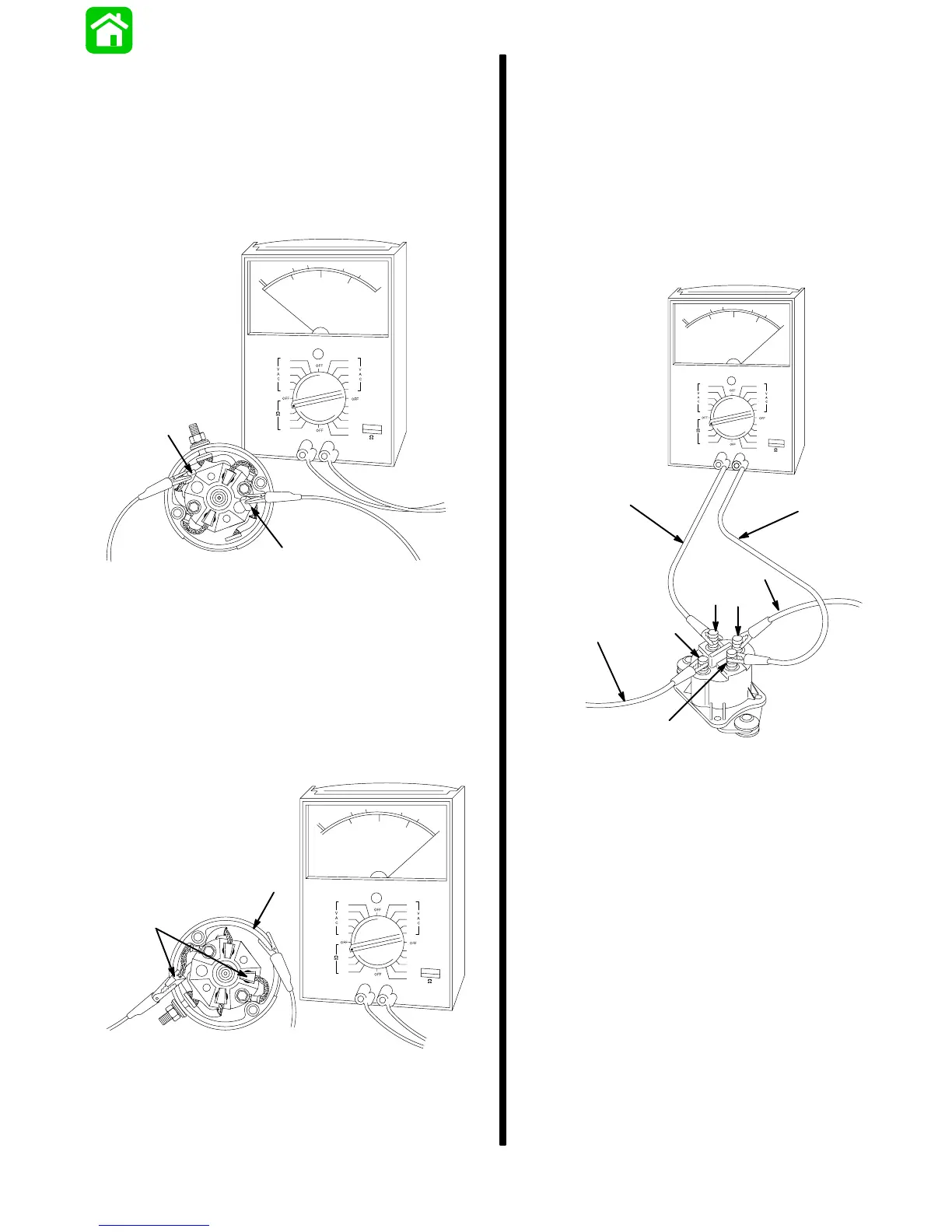
STARTER SOLENOID TEST
1. Disconnect all wires from solenoid.
2. Use an ohmmeter (R x 1 scale) and connect meter
leads between solenoid terminals 1 and 2.
3. Connect a 12-volt power supply between sole-
noid terminals 3 and 4. Solenoid should click and
meter should read 0 ohms (full continuity).
4. If meter does not read 0 ohms (full continuity), re-
place solenoid.
51809
a
b
a
b
4.
3.
2.
1.
a - 12-Volt Supply
b - VOA Leads