6A-36 POWER TRIM 90-13645--2 495
MOTOR DISASSEMBLED
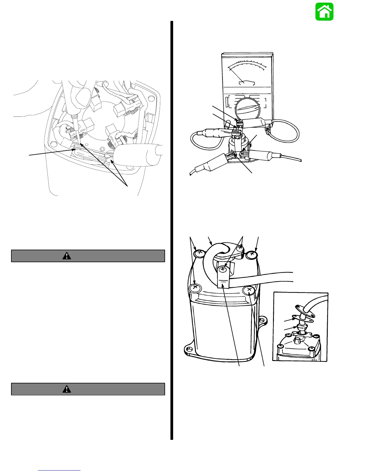
Connect Ohmmeter (R x 1 scale) leads as shown. If
switch is good, full continuity (zero ohms) will be
indicated.
If full continuity is not indicated, clean switch contact
surfaces, using an ignition point file.
18473
a
b
c
d
c - Test Leads
d - Switch Contact Surface
Recheck switch; if full continuity is not indicated, re-
place brush card. Switch is supplied on brush card.
Trim Pump Motor Test
WARNING
Do not perform this test near flammables (or
explosives), as a spark may occur when making
connections.
1. Disconnect BLUE (motor) wire and BLACK (mo-
tor) wire at solenoids.
2. Connect a 12-volt supply to motor wires [POS-
ITIVE (+) wire to BLUE (motor) wire, and NEG-
ATIVE (–) wire to BLACK (motor) wire]. Motor
should run.
3. If motor does not run, disassemble motor and
check components. Refer to “Motor Repair,”
following.
Solenoid Test
WARNING
Do not perform this test near flammable materials,
as a spark may occur while making electrical
connections.
1. Disconnect all wires from solenoid terminals.
2. Set an Ohmmeter to R x 1 scale and connect me-
ter leads to solenoid terminals 1 and 2.
3. Connect a 12-volt power supply to terminals 3 and
4. Solenoid should click and meter should read
zero (0) ohms (full continuity).
51338
1
2
3
4
4. If meter does not read zero (0) ohms, replace
solenoid.
Motor Disassembly
1. Remove screws and clamp.
a
51345
a
b
d
e
a
b
c
a - Screw (4)
b - Screw (3)
c - Clamp
d - Gasket
e - Grommet