6A-19POWER TRIM90-13645--2 495
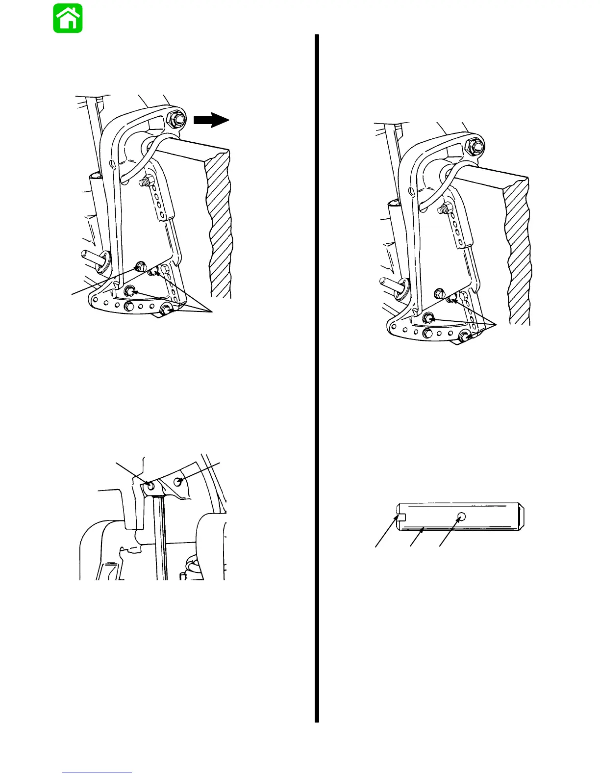
6. Remove 3 screws and washers and move
starboard transom bracket so that manual
release valve will clear bracket when power trim
is removed.
51375
a
b
c
a - Screws (3)
b - Washers (3)
c - Manual Release Valve
IMPORTANT: Cross pin (a) should not be reused.
Replace with new cross pin.
7. Drive out cross pin, push out upper swivel pin, and
remove 3 screws and washers retaining trim sys-
tem. Remove system from outboard.
51339
a
b
a - Cross Pin
b - Upper Swivel Pin
Installation
1. Paint any exposed metal surfaces to prevent
corrosion.
2. Apply Loctite 271 to screws. Install trim system,
starboard transom bracket, and tilt tube nut.
51375
a
b
a - Screw (6) Torque to 45 lb. ft. (61.0 N·m)
b - Flatwasher (6) Install one per screw
3. Use a 12 volt power source to extend tilt ram up
to align upper swivel shaft hole and end of ram.
Connect trim motor wires (BLUE wire to POS-
ITIVE (+), BLACK wire to NEGATIVE (-). If ram ex-
tends too far, retract ram by connecting GREEN
wire to POSITIVE (+).
4. Install Upper Swivel Pin with slotted end to left
(port) side of engine.
cab
a - Upper Swivel Pin
b - Slotted End
c - Cross Hole (in line with slotted end)
IMPORTANT: Cross pin should not be reused.
Install a new pin.