6A-12 POWER TRIM 90-13645--2 495
* Remote Control Equipped with Trailer Button
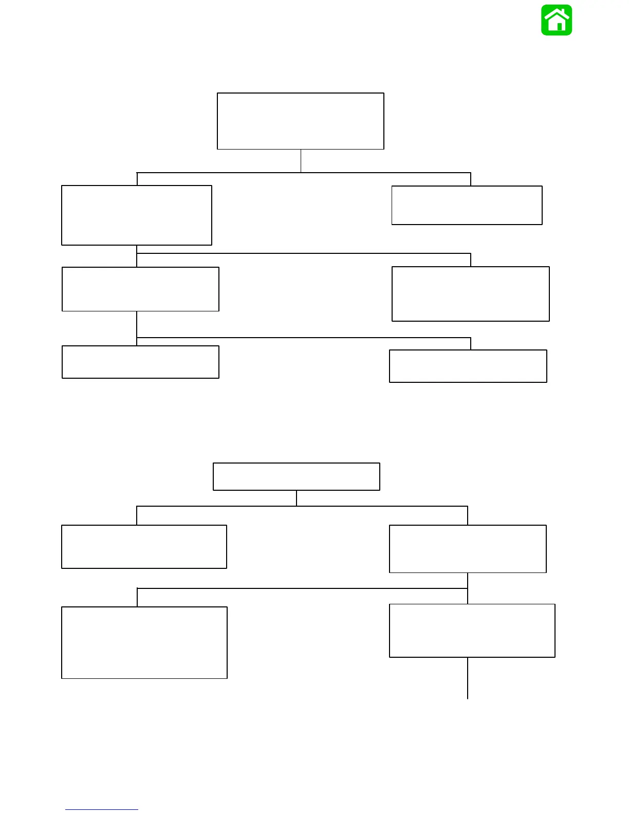
Troubleshooting the “Down,” “Up” and “Trailer” Circuits*
(All Circuits Inoperative)
* Remote Control Equipped with Trailer Button
Continuity:
Connect Voltmeter RED lead to Point
8 (push button trim switch) or Point 5
(toggle trim switch) and BLACK lead to
ground.
Fuses Not Blown:
Connect Voltmeter red lead to Point 3
and black lead to ground. Battery voltage
should be indicated.
Battery Voltage Indicated:
D Connect Voltmeter red lead to Point 7.
D Depress “Up” trim button.
Check two in-line fuses (under cowl) to see
if fuses are blown.
Troubleshooting the “Up” Circuit*
(When “Trailer” Circuit Is OK)
Use an Ohmmeter (R x 1 scale) and check
continuity of wire between Point 10 on “Up”
solenoid and Point 7 on trim button.
No Continuity:
Wire is open between Point 10 and
Point 7.
Battery Voltage Indicated:
D Check for poor connection at Point 7.
No Voltage Indicated:
Wire is open between trailer button Point
11 and trim switch Point 8 (push button
trim switch) or Point 5 (toggle trim switch).
No Voltage Indicated:
D Trim switch is defective.
Blown Fuse:
D Correct problem that caused fuse to blow.
D Replace fuse.
No Voltage Indicated:
D Check battery leads and RED leads (be-
tween engine starter motor solenoid and
Point 3) for poor connections or open
circuits.
D Check battery charge.
Battery Voltage Indicated:
D Connect Voltmeter RED lead to Point 10.
D Depress “Trailer” button and check for
battery voltage.
continued on next page . . .