90-13645--2 495 6B-35POWER TRIM
22908
1
a
b
c
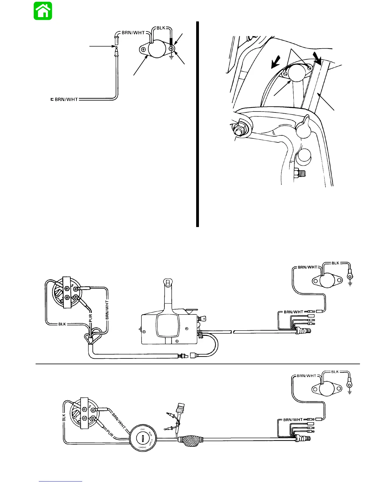
a - Trim Sender
b - Connect with screw and hex nut (coat with liquid
neoprene).
c - Rubber Sleeve (Slide over connection)
Trim Indicator Gauge Needle
Adjustment
1. Turn ignition key to “RUN” position.
2. Tilt outboard to full “IN” position. Needle of trim in-
dicator gauge should be in full “IN” position.
3. If not, tilt outboard to full “OUT” position to gain ac-
cess to trim sender and engage tilt lock lever.
4. Loosen trim sender screws and reposition trim
sender.
5. Tighten trim sender screws.
22744
a
b
c
d
e
a - Trim Sender
b - Screws, loosen to rotate sender
c - Turn sender counterclockwise to raise needle reading.
d - Turn sender clockwise to lower needle reading.
e - Tilt Lock Lever
Trim Indicator Wiring
Diagrams
Wiring Diagram - For boats equipped with Quicksilver
Commander Series Side Mount Remote Control.
Wiring Diagram - For boats equipped with Quicksilver
Ignition/Choke and Main Harness Assembly.
TRIM INDICATOR
REMOTE CONTROL
TRIM
SENDER
ENGINE
GROUND
TO ENGINE
TRIM INDICATOR
POWER TRIM
HARNESS
IGNITION/
CHOKE
SWITCH
TRIM
SENDER
ENGINE
GROUND
TO ENGINE
22908