6A-13POWER TRIM90-13645--2 495
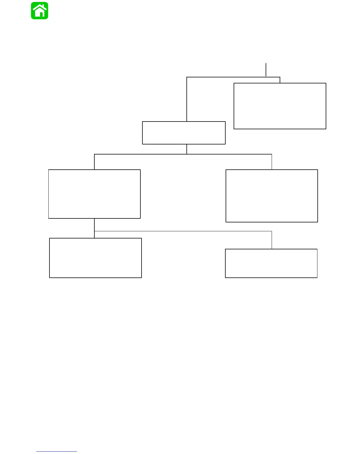
Troubleshooting the “Down,” “Up” and “Trailer” Circuits*
(All Circuits Inoperative)
* Remote Control Equipped with Trailer Button
Battery Voltage Indicated:
D Check BLACK ground wires at solenoids
for poor connection or poor ground.
D Check BLACK motor lead for poor ground
at Point 12. If wire is grounded, the pump
motor is faulty. Refer to “Motor and Elec-
trical Tests/Repair,” following.
continued from preceding page
No Voltage Indicated:
Connect RED Voltmeter lead to
Point 11, and BLACK lead to ground.
No Voltage Indicated:
Check that voltage is being supplied to
control by performing the following checks:
D DO NOT start engine.
D Turn ignition switch to “Run” position.
D Check for voltage at any instrument, using
a Voltmeter.
No Voltage Indicated:
RED wire is open between Point 14 and
terminal “b” on the back of the ignition
switch.
D Check for loose or corroded connections.
D Check for open in wire.
Battery Voltage Indicated:
There is an open circuit in each wire
[GREEN-WHITE, BLUE-WHITE, and
PURPLE-WHITE (or PURPLE)] between
trim buttons and trim pump.
D Check all trim harness connectors for
loose or corroded connections.
D Check for pinched or severed wires.
Battery Voltage Indicated:
There is an open circuit in wire between
Point 11 and terminal “b” on the back of the
ignition switch.